
Control method of photovoltaic grid-connected inverter to prevent low voltage distribution network voltage from exceeding the limit

A low-voltage distribution network and voltage over-limit technology, applied in the direction of photovoltaic power generation, electrical components, circuit devices, etc., can solve the problems of not considering the impact of photovoltaic access, increasing power grid loss, power grid loss, etc.

Active Publication Date: 2020-01-03
TAIYUAN UNIV OF TECH
View PDF5 Cites 0 Cited by
  • Summary
  • Abstract
  • Description
  • Claims
  • Application Information

AI Technical Summary

Problems solved by technology

Some scholars often use the similarity between the photovoltaic inverter and the active filter (APF) topology in the research on the control of grid-connected inverters, and perform reactive power compensation by detecting the reactive current of the load as a command, but they do not consider the control of photovoltaics. Influence of connection on grid voltage
Some scholars use the constant reactive power Q control method to suppress the voltage limit at the grid-connected point, but it does not involve how to reasonably set the reactive power reference value to adapt to the impact of load and photovoltaic output changes on the voltage
Some scholars adopt constant power control of active power output However, when the photovoltaic output is large and the voltage does not exceed the limit at the time of peak power consumption, a large amount of reactive power is also output, resulting in grid loss
Some scholars use constant power factor control However, in order to maintain a constant power factor when the voltage does not exceed the limit, the photovoltaic inverter still needs to generate a certain amount of reactive power, which also increases the loss of the grid

Method used


Image

  • Control method of photovoltaic grid-connected inverter to prevent low voltage distribution network voltage from exceeding the limit
  • Control method of photovoltaic grid-connected inverter to prevent low voltage distribution network voltage from exceeding the limit
  • Control method of photovoltaic grid-connected inverter to prevent low voltage distribution network voltage from exceeding the limit

Examples


Embodiment Construction

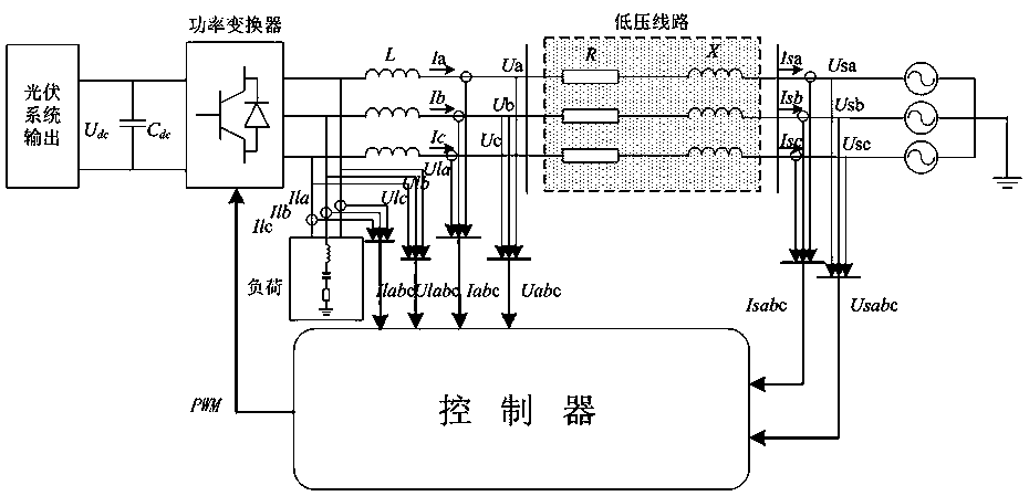
[0049] Such as figure 1 As shown in the figure, the three-phase voltage and current of the grid-connected point, the three-phase voltage and current of the grid side, and the three-phase voltage and current of the load side are input into the controller of the designed photovoltaic grid-connected inverter, and finally the control output of the inverter is obtained. PWM pulse signal.

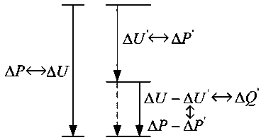
[0050] Such as figure 2 As shown in the figure, ΔP is the original light rejection amount when the grid-connected point voltage exceeds the upper limit. In order to make the voltage deviation not exceed 7%, in order to achieve the same grid-connected point voltage regulation, a strategy of matching active and reactive power is designed, that is, the higher the voltage At the upper limit, only ΔP' is needed for the light rejection amount (designed to be λ times the original light rejection amount), and the corresponding residual voltage adjustment amount ΔU-ΔU' is realized by reactive power com...


PUM


Abstract

The invention relates to a photovoltaic grid-connected inverter control method, in particular to a photovoltaic grid-connected inverter control method for preventing voltage out-of-limit of a low-voltage distribution network by considering the influence of line impedance and operating environments on a photovoltaic inverter. Voltage out-of-limit of a grid connection point of the inverter can be prevented, and light discarding amount can be decreased as far as possible by the aid of the residual capacity of the inverter on the premise of ensuring the voltage quality of the grid connection point when voltage exceeds upper limit. Compared with a traditional method, when the voltage of the grid connection point exceeds the upper limit, an active and reactive power matching method is designed by reverse thinking on the premise of ensuring the voltage quality, and the light discarding amount is decreased by the residual capacity of the inverter.

Description

technical field [0001] The invention relates to a control method of a photovoltaic grid-connected inverter, specifically a control method of a photovoltaic grid-connected inverter that prevents the voltage of a low-voltage distribution network from exceeding the limit, considering the influence of line impedance and operating environment on the photovoltaic inverter. Background technique [0002] At present, due to the increasingly severe situation of energy shortage, new energy technologies such as photovoltaics have developed rapidly. Large-scale new energy photovoltaic grid-connected operation can reduce resource investment and environmental pollution to a certain extent, but with the continuous improvement of photovoltaic penetration at all levels of the power system, the grid power quality problems caused by photovoltaic grid-connected operation cannot be underestimated . "Power Quality Supply Voltage Deviation" stipulates that the three-phase power supply voltage devi...

Claims


Application Information

Patent Timeline
Patent Type & Authority Patents(China)
IPC IPC(8): H02J3/38
CPCH02J3/383Y02E10/56
Inventor 秦文萍刘颖韩肖清王鹏王英贾燕冰孟润泉王磊李峰相莹萍
Owner TAIYUAN UNIV OF TECH
Learn More