Sand blasting control system

A control system, sandblasting technology, applied to used abrasive treatment devices, manufacturing tools, abrasives, etc. problems, to reduce labor intensity, reduce personal injury, and achieve the effect of remote control

Active Publication Date: 2017-12-08
CHANGCHUN INST OF APPLIED CHEMISTRY - CHINESE ACAD OF SCI
View PDF6 Cites 2 Cited by
  • Summary
  • Abstract
  • Description
  • Claims
  • Application Information

AI Technical Summary

Problems solved by technology

[0003] In the prior art, the sandblasting of larger workpieces is usually carried out in a sandblasting room or a sandblasting room. Operators wear heavy protective clothing to operate in the sandblasting room, which is labor intensive and inefficient; The cutting and abrasion of the surface of the workpiece will produce a large amount of dust and exhaust gas, which will cause serious harm to human health if inhaled accidentally; the sand blasting process is acco

Method used


Image

  • Sand blasting control system
  • Sand blasting control system
  • Sand blasting control system

Examples


Embodiment 1

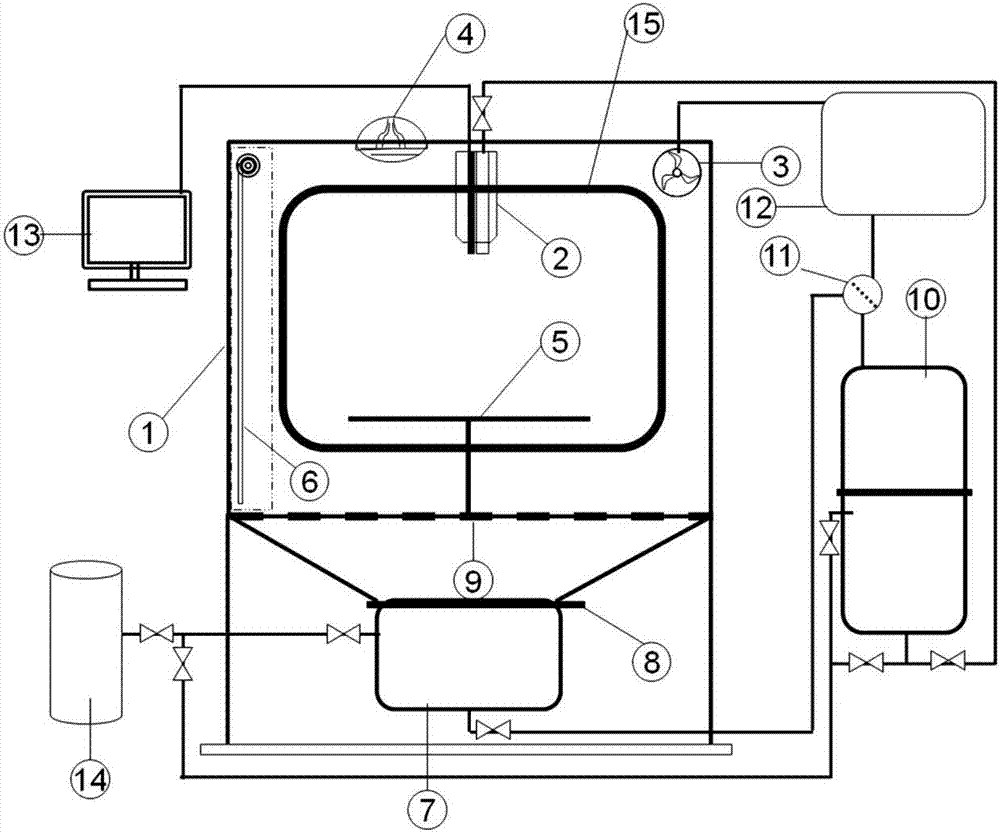
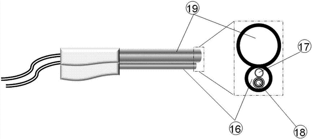
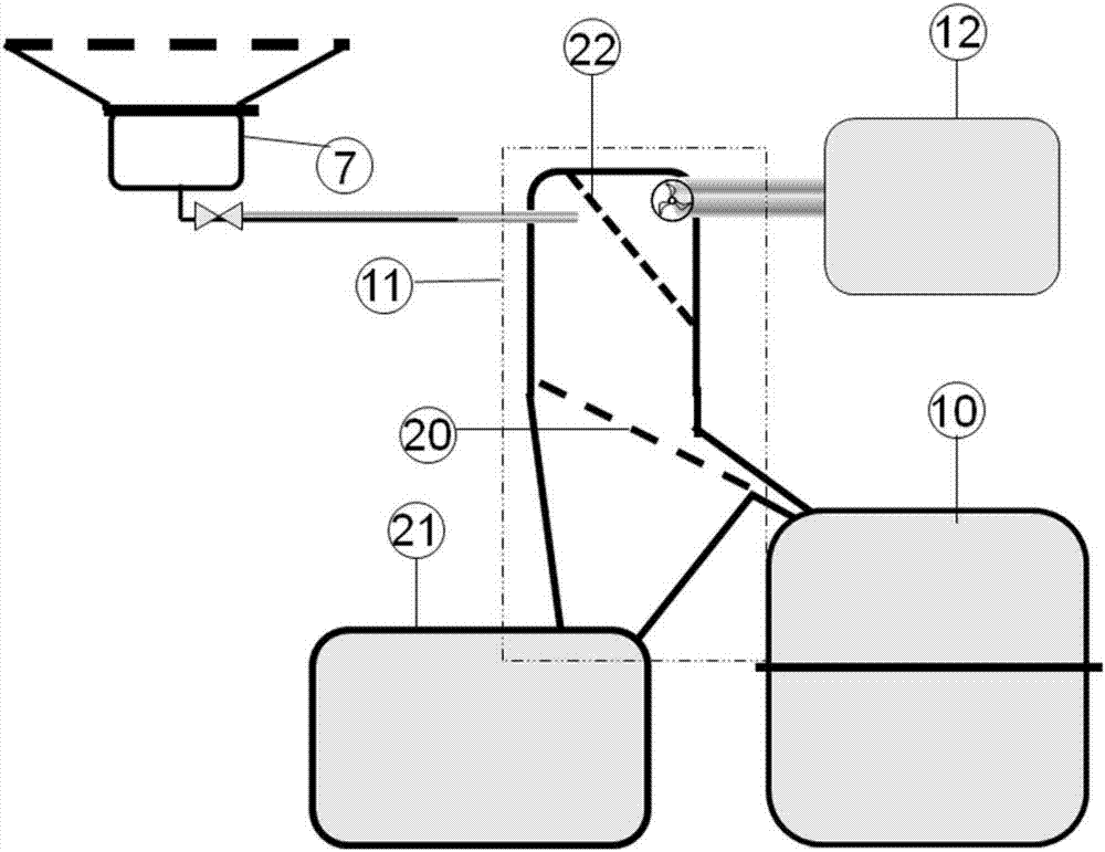
[0091] The sandblasting control system prepared according to the present invention comprises: a sandblasting room; windows are provided on the four side walls and the top of the room; transparent plastic soft curtains are provided inside the windows. There is a grid floor at the bottom of the sandblasting room; a movable workpiece carrying device is arranged on the grid floor in the sandblasting room, and the top of the sandblasting room is directly facing the workpiece carrying device, and the sand shot for blasting the workpiece is installed Spray head; the video recording device for sandblasting the surface of the workpiece is integrated on the sand blasting nozzle; Lighting unit and camera outside. The remote monitoring device is connected with the video recording device. The top of the blast booth is equipped with lighting and ventilation openings. The shot recovery device is installed at the lower part of the grid floor; the outlet of the conical collector is connected...

Embodiment 2

[0093] Using the device in Example 1, the sand shot is sprayed out through the sand shot nozzle, and the details of the surface of the workpiece are photographed by the video recording device, and transmitted to the remote monitoring equipment, so that the personnel can monitor the sandblasting effect of the details outside the box; through the movable workpiece While fixing the workpiece, the carrying device changes the position and posture of the workpiece through rotation, lifting and other actions, thereby adjusting the sandblasting effect. The light in the box can be guaranteed through the lighting equipment, and it is convenient to observe the operation situation from the outside; the anti-sand shot rebound device can buffer and offset the splashing kinetic energy of the sand shot, reducing the damage to the window, lighting equipment, box body and other equipment in the box. The scattered sand shot passes through the conical collector, and the sand shot is collected by t...


PUM


Abstract

The invention provides a sand blasting control system. The sand blasting control system comprises a sand blasting chamber, a remote monitoring device connected with a camcorder, a sand shot recovery device arranged on the lower portion of a grating floor, and a sand shot sorting device, wherein a window is arranged on the side wall of the sand blasting chamber; the grating floor is arranged at the bottom; a movable workpiece bearing device, a sand shot nozzle used for conducting sand blasting on workpieces, and a camcorder used for shooting workpiece surface sand blasting are arranged in the sand blasting chamber; the sand shot recovery device comprises a sand shot returning bin; and an inlet of the sand shot sorting device is connected with an outlet of the sand shot returning bin. According to the sand blasting control system, the detail conditions of the workpiece surfaces can be shot through the camcorder and transmitted to the remote monitoring device, and the detail sand blasting effect can be monitored outside a box conveniently; and the scattered sand shots are gathered and returned through the sand shot sorting system, subjected to dust removing, sorted and sent back to a sand blasting storage tank for cyclic utilization. Remote control over the sand blasting operation can be achieved, the labor intensity is relived, and harm to operators is reduced.

Description

technical field [0001] The invention relates to the technical field of surface treatment, in particular to a sandblasting control system. Background technique [0002] As one of the surface treatment processes with the highest efficiency and the strongest operability at present, sand blasting uses compressed air to blow ceramic sand, steel sand, quartz sand, emery and other abrasives, and spray them on the surface of the workpiece at high speed, which can realize efficient treatment of the surface of the workpiece . Through sandblasting process control and abrasive selection, different cleanliness and roughness can be obtained on the surface of the workpiece. It is widely used in: workpiece coating, pre-treatment of bonding, cleaning and polishing of rough surface of casting and forging, workpiece burr cleaning And surface beautification, and even improve the mechanical properties of parts and other fields. Especially for the pretreatment process of workpiece coating and b...

Claims


Application Information

Patent Timeline
IPC IPC(8): B24C9/00
Inventor 孙志强庞烜李帅张涵陈文啟陈学思
Owner CHANGCHUN INST OF APPLIED CHEMISTRY - CHINESE ACAD OF SCI
Why Eureka
Try Eureka