
Charging pile combination device

A combined device and charging pile technology, applied in circuit devices, battery circuit devices, charging stations, etc., can solve the problems of waste of resources and costs, inconvenient maintenance of charging piles, single payment method, etc., to save resources and costs, simple The effect of quick payment and improved security performance

Inactive Publication Date: 2017-12-08
阳谷威利克新能源科技有限公司
View PDF0 Cites 13 Cited by
  • Summary
  • Abstract
  • Description
  • Claims
  • Application Information

AI Technical Summary

Problems solved by technology

[0003] However, most of the existing charging piles are installed outdoors without sunshade and rain protection equipment. Long-term exposure to the sun or heavy rain will easily lead to excessive temperature of the charging pile or cause the device to be corroded by rain and rust, which will make the internal Electronic components are burned or lost function, poor heat dissipation performance shortens the service life of charging piles, does not effectively use natural resources to convert into usable electric energy, does not install monitoring and lighting equipment, is inconvenient to use at night, and needs to be improved in safety performance. The charging line is usually very long, and part of it is curled on the ground, which shortens its service life and needs to be replaced frequently, wasting resources and costs, and the existing charging piles are inconvenient to maintain, and the existing charging piles only have single payment method

Method used


Image

  • Charging pile combination device
  • Charging pile combination device
  • Charging pile combination device

Examples


Embodiment Construction

[0016] The following will clearly and completely describe the technical solutions in the embodiments of the present invention with reference to the accompanying drawings in the embodiments of the present invention. Obviously, the described embodiments are only some of the embodiments of the present invention, not all of them. Based on the embodiments of the present invention, all other embodiments obtained by persons of ordinary skill in the art without making creative efforts belong to the protection scope of the present invention.

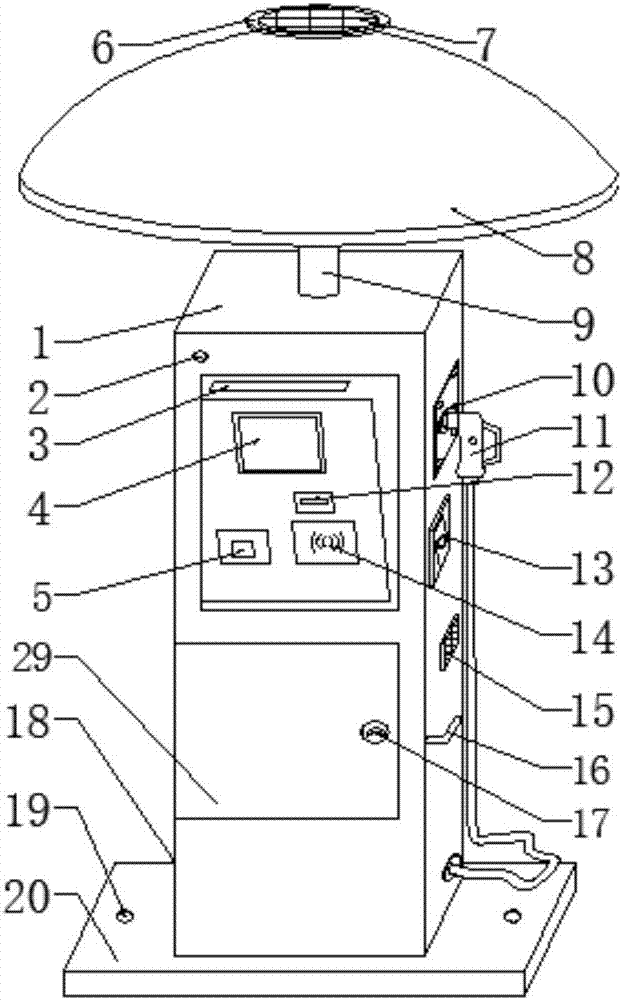
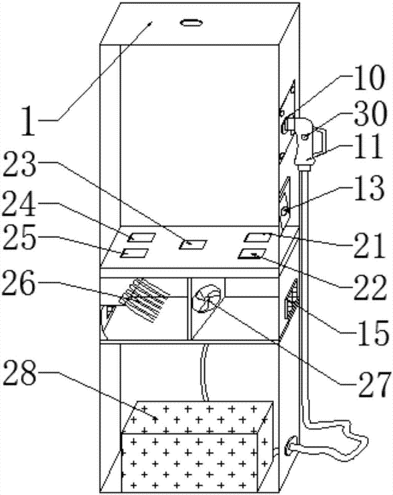
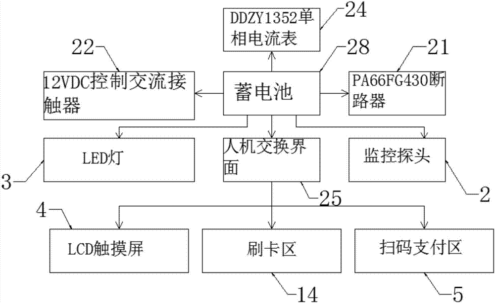
[0017] see Figure 1-2 , the present invention provides a technical solution: a charging pile combination device, including a device body 18, the device body 18 is composed of a pile body 1 arranged in the middle of the device body 18, a protective cover 8 arranged on the top of the pile body 1 and The base 20 arranged at the bottom of the pile body 1 constitutes, the pile body 1 is welded with the base 20, and is vertically arranged with the bas...


PUM


Abstract

The invention discloses a charging pile combination device. The charging pile combination device comprises a device body, and the device body is composed of a pile body, a protective cover and a base, wherein the pile body is arranged in the middle position of the device body, the protective cover is arranged at the top of the pile body and the base is arranged at the bottom of the pile body. By arranging the protective cover on the charging pile combination device, sun shading and rain sheltering can be achieved, there is no need to worry that the device is rusted caused by rain corrosion or over high internal temperature due to sun shining when being under sun or rainstorm for a long term; and a cooling pipe and a radiator fan are installed, the heat-dissipation performance is improved, and the safety performance is improved by an arranged monitoring probe; using by a user at night is convenient due to an arranged LED lamp, an electric wire at the bottom of a plug can be hung on a hanging handle, frequent replacing for the electric wire is not required, and resources and cost are saved; and maintaining for the charging pile is convenient by an arranged maintenance door, and payment is simple and quick by an additional code scanning payment area.

Description

technical field [0001] The invention relates to the technical field of charging piles, in particular to a charging pile combination device. Background technique [0002] The function of the charging pile is similar to the refueling machine in the gas station. It can be fixed on the ground or wall, and installed in public buildings (public buildings, shopping malls, public parking lots, etc.) and residential area parking lots or charging stations. Charge all models of electric vehicles. The input end of the charging pile is directly connected to the AC grid, and the output end is equipped with a charging plug for charging the electric vehicle. Charging piles generally provide two charging methods: conventional charging and fast charging. People can use a specific charging card to swipe the card on the human-computer interaction interface provided by the charging pile to perform corresponding charging methods, charging time, and cost data printing. The display screen of the ...

Claims


Application Information

Patent Timeline
IPC IPC(8): B60L11/18H02J7/35H05K7/20H05K7/00
CPCB60L53/31B60L53/665H02J7/35H05K7/00H05K7/20709Y02T10/70Y02T10/7072Y02T90/12
Inventor 王岩
Owner 阳谷威利克新能源科技有限公司
Learn More