Motor vehicle track control method and motor vehicle navigation coordinate system establishment method

A navigation coordinate system and trajectory control technology, applied in the field of car navigation, can solve the problems of bumping into the roadside guardrail, getting out of the front, steering wheel deflection, etc., and achieve the effect of preventing rear-end collision and bumping into the guardrail, beautiful appearance, and small precision error

Pending Publication Date: 2017-12-08
SIHONG ZHENGXING MEDICAL TECH CO LTD
View PDF10 Cites 14 Cited by
  • Summary
  • Abstract
  • Description
  • Claims
  • Application Information

AI Technical Summary

Problems solved by technology

When driving at high speed, the judgment of the distance between vehicles needs to be estimated by the driver's visual estimation, and if the judgment is not timely, it may easily cause rear-end collision
There are often drivers who doze off, pick up their mobile phones, or turn their heads, causing their eyes to leave the front for a short time, or the steering wheel is eccentric. At a speed of 100 kilometers per hour, they will travel about 30 meters in one second, and rear-end collisions or collisions are likely to occur. hit the curb
These problems can be warned in advance by installing car radar on the car, and the current parking system operates at low speeds and is useless at high speeds

Method used


Image

  • Motor vehicle track control method and motor vehicle navigation coordinate system establishment method
  • Motor vehicle track control method and motor vehicle navigation coordinate system establishment method
  • Motor vehicle track control method and motor vehicle navigation coordinate system establishment method

Examples


Embodiment Construction

[0056] The technical solutions of the present invention will be further described below in conjunction with the accompanying drawings and embodiments.

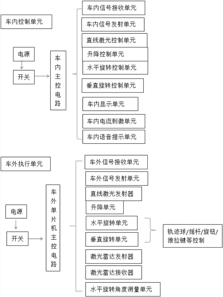
[0057] Such as figure 1 Shown is the motor vehicle laser navigation system according to the present invention, which includes an in-vehicle control unit, an out-of-vehicle execution unit and a fixture, and the fixture is used to install the out-of-vehicle execution unit.

[0058] The control unit in the car includes power supply, switch and the main control circuit in the car. The main control circuit in the car includes the signal receiving unit in the car, the signal transmitting unit in the car, the linear laser control unit, the lifting control unit, the horizontal rotation control unit, and the vertical rotation control unit. unit, in-vehicle display unit, in-vehicle current stimulation unit and in-vehicle voice prompt unit. The control unit in the car can be installed on the steering wheel, the air outlet of the air con...


PUM


Abstract

The invention discloses a motor vehicle track control method and a motor vehicle navigation coordinate system establishment method. Two reference points are selected at random, and the distance between the two points is calculated; any one point is taken as the original point, and the connecting line of the two points is taken as the X axis to establish an XY axis coordinate system; based on the established coordinate system, laser navigation equipment of a motor vehicle emits a linear laser by the angle theta, and the motor vehicle linearly backs up along the deflection angle of a vehicle body; and when the liner laser scans the reference point which is not the original point, a steering wheel is turned to the fixed position to change the travelling track. The motor vehicle track control method and the motor vehicle navigation coordinate system establishment method can be used in any garage, parking lot and open space, and the using range is wide; interference from the surrounding environment is small, and parking can be achieved at any angle and position; the accurate and safe effects are achieved, mounting and dismounting are convenient, suitable clamp tools can be selected according to vehicle types and are directly clamped on rearview mirrors, a power source is carried, and the vehicle route does not need to be changed; and the shape is attractive, extra wind resistance is not generated, a protective shell and the outer rearview mirrors are integrated into a whole, and the outer rearview mirrors can be laid flat or retracted into the protective shell.

Description

technical field [0001] The invention belongs to the technical field of car navigation, and in particular relates to a method for controlling a vehicle trajectory and a method for establishing a vehicle navigation coordinate system. Background technique [0002] With the development of the automobile industry, the number of automobiles and related accidents in my country has increased rapidly. According to relevant statistics, 40% of accidents are related to parking. The compulsory driving school test item "reversing into storage" has always been hailed as an "examination killer". Even if a driver's license is obtained, novice drivers often encounter more complicated reversing situations in reality. Because there is no suitable reference object, or it is difficult to observe the environment behind the vehicle, the spatial perception ability is insufficient, which can easily lead to rear collisions, body scratches and even more serious accidents. [0003] At present, the car ...

Claims


Application Information

Patent Timeline
Patent Type & Authority Applications(China)
IPC IPC(8): B62D15/02B60Q9/00
CPCB62D15/0285B60Q9/00
Inventor 郑杨郑兴
Owner SIHONG ZHENGXING MEDICAL TECH CO LTD
Why Eureka
Try Eureka