Rising and landing machine for power line repair

An electric power emergency repair and lowering technology, applied in elevators, elevators in buildings, lifting devices, etc., can solve the problems of easy to cause great danger, inconvenient to carry tools, disadvantageous to control costs, etc., and achieve balanced friction and convenience. Overhaul and maintenance, the effect of avoiding dependence on electricity

Inactive Publication Date: 2017-12-08
广西博腾恒泰智能科技有限公司
View PDF5 Cites 0 Cited by
  • Summary
  • Abstract
  • Description
  • Claims
  • Application Information

AI Technical Summary

Problems solved by technology

[0002] Power and electrical equipment is widely used, and there are many installation locations, some of which are installed in indoor power distribution rooms. This kind of equipment is usually easy to maintain and does not need to use lifting facilities, such as ladders, lifting vehicles, etc., but Some are also installed at high places, such as on an outdoor high-altitude iron frame. When maintenance at high places is required, the existing ones usually use some climbing tools, which are prone to great danger when people climb, or use ladders Climbing, but power and electrical equipment is usually fixed at a certain end point and does not need to be moved. After the maintenance is completed, the ladder needs to be dragged away for storage, and the lower end of the ladder is movable. If no one supports it, it is easy to slip and fall. It is inconvenient to carry tools, and some lift trucks are used for maintenance. Although lift trucks are convenient to use, they are not conducive to cost control

Method used


Image

  • Rising and landing machine for power line repair
  • Rising and landing machine for power line repair
  • Rising and landing machine for power line repair

Examples


Embodiment Construction

[0025] All features disclosed in this specification, or steps in all methods or processes disclosed, may be combined in any manner, except for mutually exclusive features and / or steps.

[0026] Any feature disclosed in this specification (including any appended claims, abstract and drawings), unless expressly stated otherwise, may be replaced by alternative features which are equivalent or serve a similar purpose. That is, unless expressly stated otherwise, each feature is one example only of a series of equivalent or similar features.

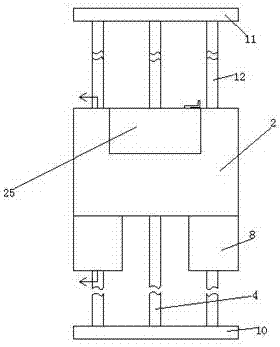
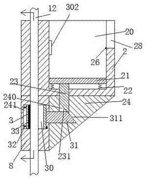
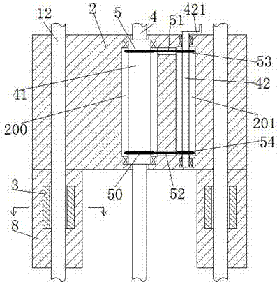
[0027] Such as Figure 1-5 As shown, a kind of lifting machine for electric power emergency repair of the present invention comprises a base plate 10 fixedly installed on the bottom surface and a top plate 11 fixedly installed on the high-altitude iron frame, between the base plate 10 and the top plate 11 is fixedly installed The two guide rods 12 corresponding to the left and right and the take-off and landing spiral rod 4 between the two gu...


PUM


Abstract

A lifting machine for electric emergency repair, comprising a base plate fixedly installed on the bottom surface and a top plate fixedly installed on the high-altitude iron frame, two guide rods corresponding to the left and right are fixedly installed between the base plate and the top plate, and two The take-off and landing spiral rod between the guide rods, the take-off and landing platform is installed on the take-off and landing screw-shaped rod, and the left and right sides of the take-off and landing platform are correspondingly provided with guide holes, the guide holes are matched with the guide rod, and the guide rod A guide sleeve is also slidably installed on the top, and the upper end surface of the guide sleeve is fixedly connected with the lower end surface of the lifting platform. A wedge panel is also fixedly installed between the front end of the guide sleeve and the bottom end of the lifting platform. The slot and the vertical slot connected with the horizontal slot, a sliding plate is installed in the accommodation cavity in the landing platform to slide up and down, and a sliding slot extending front and back is arranged in the guide sleeve, and the sliding slot is installed in the sliding slot. There is a sliding frame, which is provided with a hollow groove that allows the guide rod to penetrate, and the rear end wall of the hollow groove is set as an annular surface, and an annular pressing piece is fixedly installed on the annular surface.

Description

technical field [0001] The invention relates to the field of electric power facilities, in particular to a lifting machine for emergency repair of electric power. Background technique [0002] Power and electrical equipment is widely used, and there are many installation locations, some of which are installed in indoor power distribution rooms. This kind of equipment is usually easy to maintain and does not need to use lifting facilities, such as ladders, lifting vehicles, etc., but Some are also installed at high places, such as on an outdoor high-altitude iron frame. When maintenance at high places is required, the existing ones usually use some climbing tools, which are prone to great danger when people climb, or use ladders Climbing, but power and electrical equipment is usually fixed at a certain end point and does not need to be moved. After the maintenance is completed, the ladder needs to be dragged away for storage, and the lower end of the ladder is movable. If no ...

Claims


Application Information

Patent Timeline
IPC IPC(8): B66B9/02B66B7/02B66B11/04B66B3/00B66F11/04
CPCB66B9/025B66B3/002B66B7/02B66B11/0415B66F11/04
Inventor 黎珏良
Owner 广西博腾恒泰智能科技有限公司
Why Eureka
Try Eureka