Liquid ammonia vaporizer and working method thereof

A vaporizer and liquid ammonia technology, which is applied in the field of liquid ammonia vaporization, can solve the problems of large equipment volume, poor liquid ammonia vaporization effect, and low safety, and achieve the effects of improving the boiling heat transfer coefficient, preventing frosting, and expanding the vaporization space

Pending Publication Date: 2017-12-08
ACRE COKING & REFRACTORY ENG CONSULTING CORP DALIAN MCC
View PDF10 Cites 1 Cited by
  • Summary
  • Abstract
  • Description
  • Claims
  • Application Information

AI Technical Summary

Problems solved by technology

However, the currently commonly used ammonia vaporization devices generally have the pro

Method used


Image

  • Liquid ammonia vaporizer and working method thereof
  • Liquid ammonia vaporizer and working method thereof

Examples


Embodiment Construction

[0022] The specific embodiment of the present invention will be further described below in conjunction with accompanying drawing:

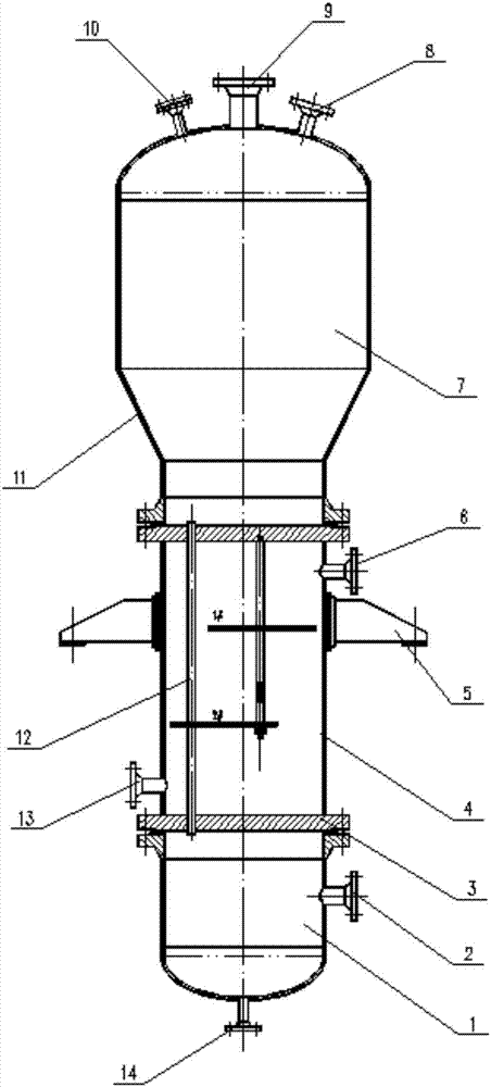
[0023] Such as figure 1 As shown, the ammonia vaporizer of the present invention includes a tube box 1, a heat exchange section 4 and a vaporization section 7 arranged sequentially from bottom to top; the bottom of the tube box 1 is provided with a vent 14, and the middle part is provided with a liquid ammonia inlet 2 ; The heat exchange section 4 is composed of a tube sheet 3, a heat exchange tube 12 and a shell-side cylinder, and the heat exchange section 4 is separated from the vaporization section 7 and the tube box 1 by upper and lower tube sheets 3 respectively, and the heat exchange tube 12 is vertically arranged in the shell-side cylinder of the heat exchange section 4, its upper end passes through the upper tube sheet 3 to communicate with the vaporization section 4, and its lower end passes through the lower tube sheet 3 to communicate w...


PUM


Abstract

The invention relates to a liquid ammonia vaporizer and a working method thereof. The liquid ammonia vaporizer comprises a pipe box, a heat exchange section and a vaporization section arranged in sequence from bottom to top; an emptying port is formed in the bottom of the pipe box; a liquid ammonia inlet is formed in the middle part of the pipe box; the heat exchange section consists of pipe plates, a heat exchange pipe and a shell pass cylinder; the heat exchange section is separated from the vaporization section and the pipe box through the upper and lower pipe plates; the heat exchange pipe is vertically arranged in the shell pass cylinder of the heat exchange section, the upper end thereof penetrates through the pipe plate on the upper side to communicate with the vaporization section, and the lower end penetrates through the pipe plate on the lower side to communicate with the pipe box; a steam inlet is formed in one side of the lower part of the shell pass cylinder, and a condensed water outlet is formed in the other side of the upper part; the lower part of the vaporization section is a cone section; and an ammonia gas outlet, a safety valve joint and a pressure gauge joint are arranged at the top. The liquid ammonia vaporizer has the advantages of small equipment size, low weight, good vaporization effect of liquid ammonia and high safety.

Description


Claims


Application Information

Patent Timeline
Owner ACRE COKING & REFRACTORY ENG CONSULTING CORP DALIAN MCC
Why Eureka
Try Eureka