Micromechanical gyroscope for nano-optical grating

A micro-machined gyroscope and nano-grating technology, which is applied in the field of micro-inertial navigation, can solve the problems such as the influence of the performance of the capacitive detection type micro-gyroscope, the complex growth process of piezoelectric materials, and the inability to perform high-temperature operation, and achieves obvious Offset effect and reasonable structure design. , the effect of high sensitivity

Pending Publication Date: 2017-12-08
ZHONGBEI UNIV
View PDF8 Cites 8 Cited by
  • Summary
  • Abstract
  • Description
  • Claims
  • Application Information

AI Technical Summary

Problems solved by technology

However, the parasitic capacitance inside the sensor will have a certain impact on the performance of the capacitive detection micro-gyroscope. In order to reduce the influence of the parasitic capacitance, it puts forward higher requirements on the detection accuracy and anti-interference ability of the interface circuit.
The piezoelectric detection MEMS gyroscope has the characteristics of small size, direct output voltage signal, and easy compatibility with ICs. However, the output voltage signal of the piezoelectric detection MEMS gyroscope is small, and the growth process of the piezoelectric material is complicated, so it cannot be operated at high temperature.

Method used


Image

  • Micromechanical gyroscope for nano-optical grating
  • Micromechanical gyroscope for nano-optical grating
  • Micromechanical gyroscope for nano-optical grating

Examples


Embodiment Construction

[0033] Embodiments of the present invention are described in detail below, examples of which are shown in the drawings, wherein the same or similar reference numerals designate the same or similar elements or elements having the same or similar functions throughout. The embodiments described below by referring to the figures are exemplary only for explaining the present invention and should not be construed as limiting the present invention.

[0034] In the description of the present invention, it should be noted that unless otherwise specified and limited, the terms "connected" and "connected" should be understood in a broad sense, for example, it can be a fixed connection, a detachable connection, or an integral Ground connection; it can be a mechanical connection or an electrical connection; it can be a direct connection or an indirect connection through an intermediary, and it can be the internal communication of two components. Those of ordinary skill in the art can under...


PUM


Abstract

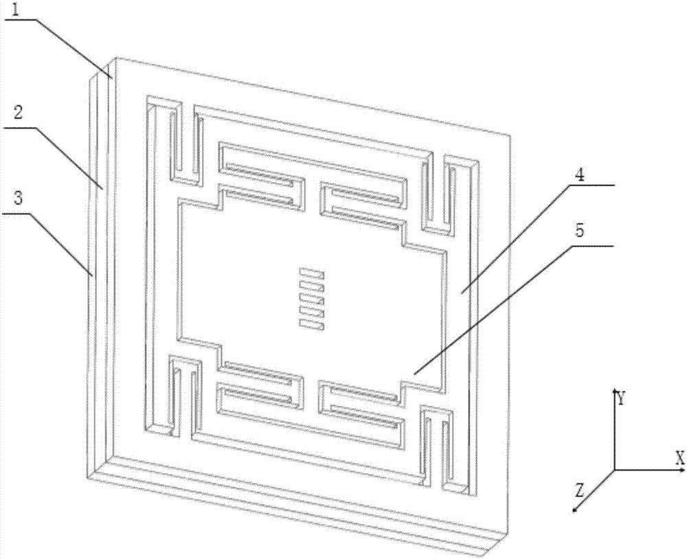
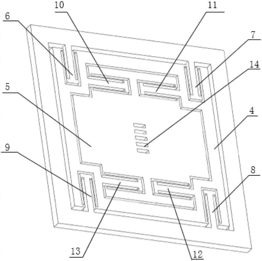
The invention relates to a micromechanical gyroscope for nano-optical grating. The micromechanical gyroscope mainly structurally comprises an upper base plate, a bonding frame body, a lower base plate, a support frame body, an outer mass block, an inner mass block, a driving mechanism, detection mechanisms, movable optical gratings, a driving magnet body, a detection magnet body and fixed optical gratings, wherein the support frame body, the inner mass block, the outer mass block, the driving mechanism and the detection mechanisms are arranged on the upper base plate, the movable optical gratings are arranged in the center of the inner mass block, the bonding frame body is fixedly connected with the lower base plate and the upper base plate, the driving magnet body, the detection magnet body and the fixed optical gratings are symmetrically arranged on the lower base plate, and the fixed optical gratings are arranged in the center of the lower base plate. The micromechanical gyroscope is of a symmetrical integral structure, is used for detecting a weak Coriolis force by virtue of an optical effect and has the advantages of high detection precision, reasonable and compact structure, high sensitivity and good reliability; and compared with the prior art, the detection precision is increased by 1-2 magnitude orders.

Description

technical field [0001] The invention relates to a nanometer grating micromechanical gyroscope, which belongs to the technical field of micro-inertial navigation. Background technique [0002] Micromechanical gyroscope is a high-tech developed in the early 1980s for both military and civilian purposes. Compared with traditional gyroscopes, it has small size, low power consumption, low cost, easy mass production, high sensitivity, and overload resistance. It can be embedded in electronics, information and intelligent control systems, which greatly reduces the size and cost of the system, and greatly improves the overall performance, which is in line with the development direction of product informatization. The field of national defense has a wide application prospect, and more and more people pay attention to it. [0003] At present, the detection methods of micro-mechanical gyroscopes mainly include capacitance and piezoelectric detection methods. Capacitive detection micro...

Claims


Application Information

Patent Timeline
Patent Type & Authority Applications(China)
IPC IPC(8): G01C19/5733
CPCG01C19/5733
Inventor 李孟委耿浩梁洲鑫吴倩楠李秀源
Owner ZHONGBEI UNIV
Why Eureka
Try Eureka