Smart umbrella stand for receiving sharing umbrella

A technology of sunny umbrellas and smart umbrellas, applied in the field of umbrella stands, can solve the problems of unavailable and complicated operation, and achieve the effect of simple operation, simple and compact structure, and fast and efficient rental services

Inactive Publication Date: 2017-12-08
成都源来来科技有限公司
View PDF0 Cites 4 Cited by
  • Summary
  • Abstract
  • Description
  • Claims
  • Application Information

AI Technical Summary

Problems solved by technology

[0005] Aiming at the problems in the above-mentioned prior art that the operation is complicated and cannot provide Internet sharing and leasing functions, the present invention provides a smart umbrella that can control the locking and unlocking of umbrellas through the connection operation between mobile phones and remote servers, and can store and place shared umbrellas. shelf

Method used


Image

  • Smart umbrella stand for receiving sharing umbrella
  • Smart umbrella stand for receiving sharing umbrella
  • Smart umbrella stand for receiving sharing umbrella

Examples


Embodiment 1

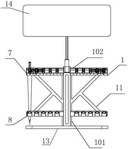
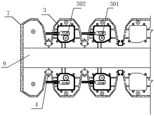
[0035] A kind of intelligent umbrella stand 1 for accommodating shared sunny umbrellas of the present embodiment, such as figure 1 As shown, its main structure is an umbrella stand 1 capable of placing a sunny umbrella. In the umbrella stand 1, a controller 2 and a communication module 5 connected to the controller 2 are provided. The communication module 5 adopts an LTE module or a GSM module. Through the communication module 5, it communicates with the main server installed remotely. The umbrella stand 1 is provided with a plurality of locking machines 3 for clamping and capable of locking function, and the umbrella handle of a sunny umbrella that is adapted to it is provided with a protrusion that cooperates with the locking machines 3 . Then on the umbrella stand 1, corresponding to each locking machine 3, a microswitch 4 is provided, and the effect of triggering feedback locking is reached by contacting the umbrella handle of the sunny umbrella with the microswitch 4. On...

Embodiment 2

[0039] This embodiment is further defined on the basis of the above embodiments, as Figure 4 As shown, in this embodiment, the umbrella stand 1 is optimized, and the umbrella stand 1 is provided with a sinker 6 corresponding to each side of the locking machine 3, and the micro switch 4 is arranged on the inner bottom surface of the sinker 6 . The sunk groove 6 can clamp the bump provided on the umbrella handle, and when the bump touches the micro switch 4 and pushes the pressing piece of the micro switch 4 into the micro switch 4 completely so that the micro switch 4. When the internal circuit is changed for feedback, the locking machine 3 and the bump just fit. The controller 2 then controls the locking machine 3 to lock the umbrella handle. Other parts of this embodiment are the same as those of the foregoing embodiment, and will not be repeated here.

Embodiment 3

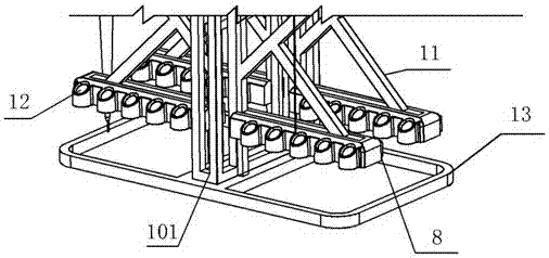
[0041] This embodiment is further defined on the basis of the above embodiments, as figure 2As shown, the umbrella stand 1 is now specifically defined. The umbrella stand 1 includes a main control box 101 fixed on the ground. The main control box 101 is a door-shaped box structure, and its bottom can be fixed on the ground. Two rows of umbrella fixing frames 102 are arranged symmetrically on both sides of the main control box 101, and the umbrella fixing frames 102 include locking boxes 7 and fixing rods 8 parallel to each other. The lock box 7 and the end faces of the fixed rod 8 on the same side are fixed on one side of the main control box 101 . The locking box 7 is arranged on the top, and two or more sinking grooves 6 are equidistantly arranged along the straight line where the longest side of the locking box 7 is located, that is, two vertical surfaces of the locking box 7 are provided with There is a row of sinking grooves 6, and a locking machine 3 is provided corres...


PUM


Abstract

The invention discloses an intelligent umbrella stand for accommodating shared umbrellas, which includes an umbrella stand for placing umbrellas and a controller for controlling the umbrella stand to lock the umbrellas. The umbrella stand is provided with at least one To lock the umbrella handle of the sunny umbrella and the lock machine connected to the controller, each lock machine on the umbrella frame is provided with a micro switch connected to the controller; the controller is also connected to a communication module. The present invention has a simple and compact structure, and is the executive mechanism of the entire shared umbrella system. By arranging the devices of the present invention in a certain area, and then connecting each device with a remote main server to form a shared umbrella management leasing system, it can be used in a certain area. The rental service of shared umbrellas is provided in the area to facilitate people's travel.

Description

technical field [0001] The invention relates to the field of umbrella stands, in particular to an intelligent umbrella stand for accommodating shared sunny umbrellas. Background technique [0002] In modern society, almost everyone has a smart phone. The popularity of smart phones has brought great convenience to people's life and travel, and even changed people's way of life. Through the Internet and smart phones, people can communicate with friends and family members anytime and anywhere to realize remote communication, and through data transmission through smart phones, people can get the latest information at the first time. Through the rapid transmission of data, the previous inherent way of life is broken. For example, only cash or bank cards can be used for payment, but now mobile phones can be directly used for mobile payment. Through the rapid popularization of mobile payment and technological updates, a new type of life pattern that has become popular in recent ye...

Claims


Application Information

Patent Timeline
Patent Type & Authority Applications(China)
IPC IPC(8): G05B19/042
CPCG05B19/0423G05B2219/25257
Inventor 杨利华
Owner 成都源来来科技有限公司
Why Eureka
Try Eureka