can signal wake-up circuit
A wake-up circuit and signal technology, applied in circuit devices, battery circuit devices, current collectors, etc., can solve the problems of complex signal wake-up methods and high cost, and achieve the effects of control system cost, fast response, and simple control mode
- Summary
- Abstract
- Description
- Claims
- Application Information
AI Technical Summary
Problems solved by technology
Method used
Image
Examples
Embodiment Construction
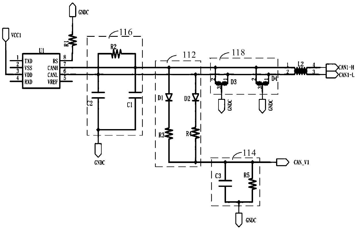
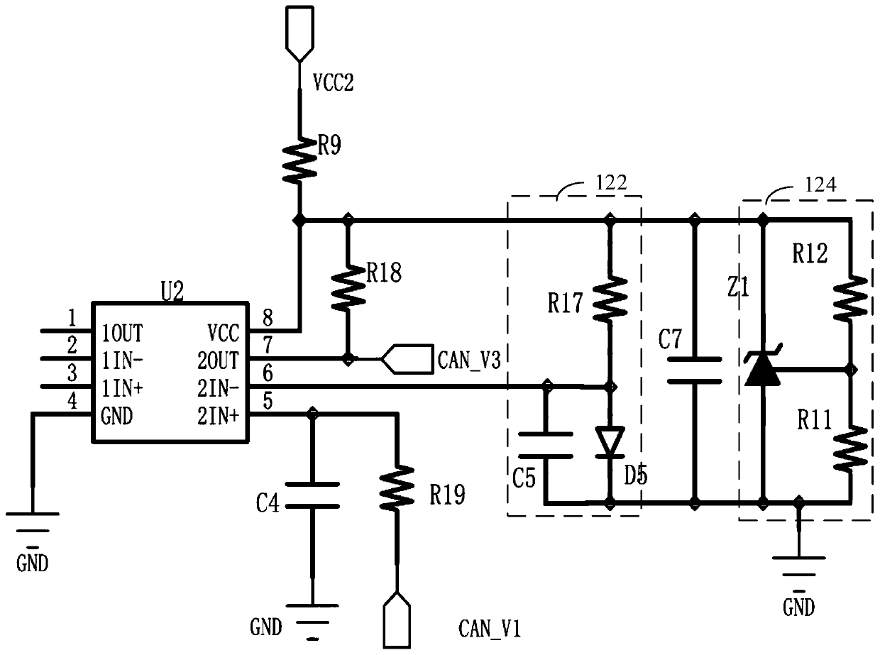
[0013] In one embodiment, such as figure 1 As shown, a CAN signal wake-up circuit includes a voltage comparison circuit 120 and a CAN signal detection circuit 110 for connecting to a CAN network. The CAN signal detection circuit 110 is connected to the first input terminal of the voltage comparison circuit 120 and is also used for connecting to a CAN network. 300. The second input terminal of the voltage comparison circuit 120 is used to receive an external voltage, and the output terminal of the voltage comparison circuit 120 is also used to connect to the device 200 to be woken up.
[0014] Specifically, the CAN signal detection circuit 110 is used to receive the CAN signal in the CAN network 300, convert the CAN signal into a first voltage signal CAN_V1, and output the first voltage signal CAN_V1 to the first input terminal of the voltage comparison circuit 120; The comparison circuit 120 receives the first voltage signal CAN_V1 and the external voltage VCC2, and outputs a ...
PUM
 Abstract
Description
Claims
Application Information
 - R&D
- Intellectual Property
- Life Sciences
- Materials
- Tech Scout
- Unparalleled Data Quality
- Higher Quality Content
- 60% Fewer Hallucinations
Browse by: Latest US Patents, China's latest patents, Technical Efficacy Thesaurus, Application Domain, Technology Topic, Popular Technical Reports.
© 2025 PatSnap. All rights reserved.Legal|Privacy policy|Modern Slavery Act Transparency Statement|Sitemap|About US| Contact US: help@patsnap.com


