MMC DC voltage outer loop controller and generation method thereof
A DC voltage, DC side voltage technology, applied in the direction of AC power input conversion to DC power output, electrical components, power transmission AC network, etc., can solve the problems of limited application scope, low accuracy, low universality, etc. High model accuracy, high precision effects
- Summary
- Abstract
- Description
- Claims
- Application Information
AI Technical Summary
Problems solved by technology
Method used
Image
Examples
Embodiment 1
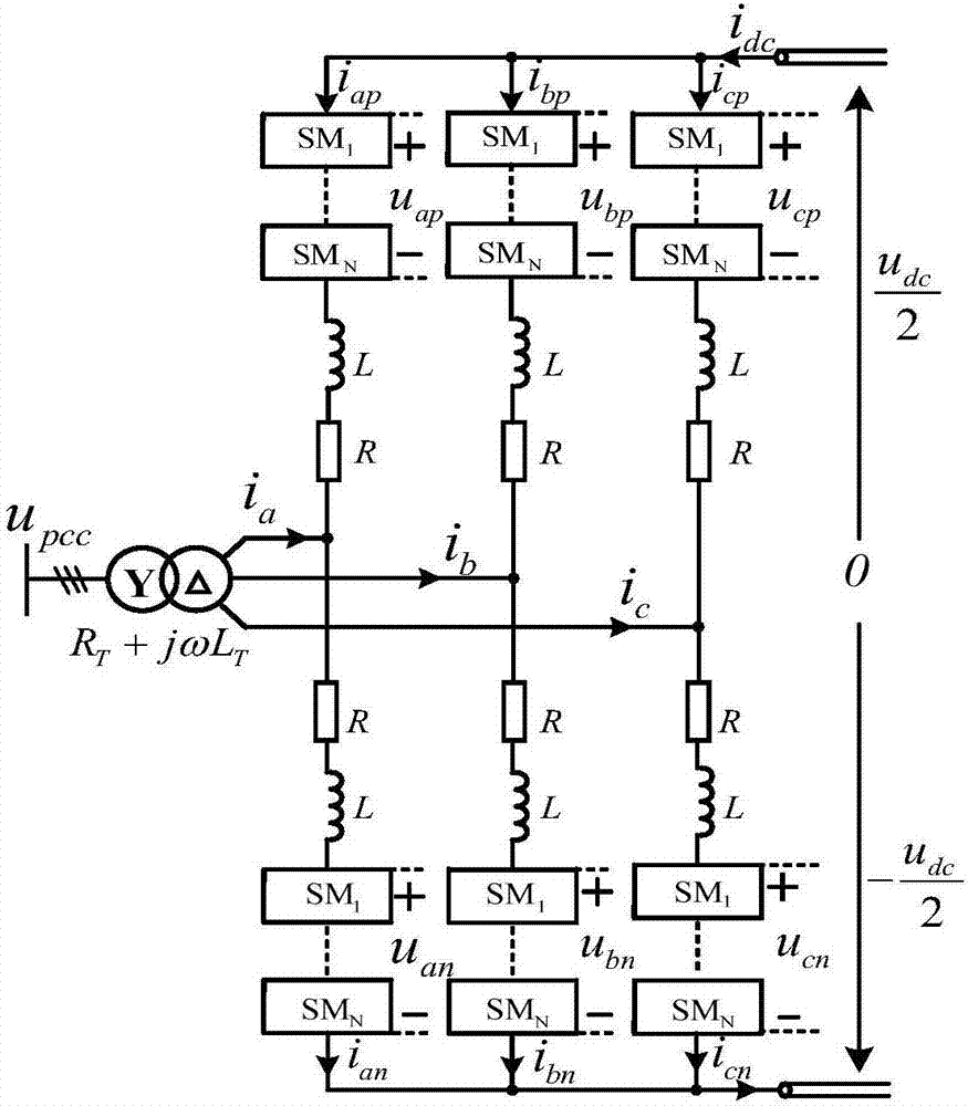
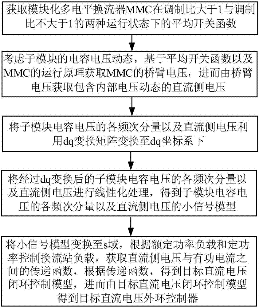
[0117] The load connected to the converter is a rated resistance R L , its resistance is 400Ω, such as Figure 4 As shown, the system has no negative level output, that is, the maximum modulation ratio of the system is 1, and the output voltage of the bridge arm is always greater than 0, such as Figure 5 shown. For the case with a constant power resistive load, the exact DC voltage u dc and active current i d The transfer function between them is:
[0118]
[0119] Among them, Δu dc is the disturbance of DC side voltage, Δi d is the disturbance of the d-axis component of the AC side current (i.e. the active current), u c_1d0 is the steady-state quantity of the d-axis component of the fundamental frequency component of the sub-module capacitor voltage, u c_1q0 is the steady-state quantity of the q-axis component of the fundamental frequency component of the sub-module capacitor voltage, u dc0 is the steady-state quantity of DC side voltage, R L is the load resistan...
Embodiment 2
[0128] The load connected to the converter is a rated resistance R L , the resistance value is 400Ω, the system has a negative level output, and the maximum modulation ratio of the system is set to 2, the output voltage of the bridge arm will have a negative value, such as Figure 8 shown. For the case with rated resistive load, the DC voltage u dc and active current i d The simplified transfer function between is:
[0129]
[0130] Among them, Δu dc is the disturbance of DC side voltage, Δi d is the disturbance of the d-axis component of the AC side current (i.e. the active current), u dc0 is the steady-state quantity of DC side voltage, u cd0 is the steady-state quantity of the d-axis component of the PCC point voltage, R L is the load resistance, C is the capacitance value of the sub-module, N is the number of sub-modules of each bridge arm, m max is the maximum modulation ratio allowed by the system, and s is the Laplacian operator.
[0131] In the traditional ...
Embodiment 3
[0136] Set the load connected to the converter controlled by constant DC voltage as a converter station controlled by constant power, such as Figure 10 shown. For the case of a converter station with constant power control, the DC voltage u dc and active current i d The simplified transfer function between is:
[0137]
[0138] Among them, Δu dc is the disturbance of the DC side voltage of the converter station controlled by a constant DC voltage, Δi d is the disturbance of the d-axis component (i.e. active current) of the AC side current of the converter station controlled by a constant DC voltage, u dc0 is the steady-state quantity of the DC side voltage of the converter station controlled by the constant DC voltage, u cd0 is the steady-state quantity of the d-axis component of the PCC point voltage of the converter station controlled by constant DC voltage, C is the sub-module capacitance value of the converter station controlled by constant DC voltage, and C' is t...
PUM
 Abstract
Description
Claims
Application Information
 - R&D
- Intellectual Property
- Life Sciences
- Materials
- Tech Scout
- Unparalleled Data Quality
- Higher Quality Content
- 60% Fewer Hallucinations
Browse by: Latest US Patents, China's latest patents, Technical Efficacy Thesaurus, Application Domain, Technology Topic, Popular Technical Reports.
© 2025 PatSnap. All rights reserved.Legal|Privacy policy|Modern Slavery Act Transparency Statement|Sitemap|About US| Contact US: help@patsnap.com


