Speed-regulating groove component

A technology of speed regulation and components, applied in the field of medical device accessories and medical devices, can solve the problems of large influence and large opening of open grooves, and achieve the effect of reducing process influence, maintaining accuracy and stable quality

Inactive Publication Date: 2017-12-12
GUANGZHOU JIANZHITANG MEDICAL INSTR CO LTD
View PDF0 Cites 0 Cited by
  • Summary
  • Abstract
  • Description
  • Claims
  • Application Information

AI Technical Summary

Problems solved by technology

Especially in the speed-regulating groove section with a large flow rate, the opening of the open groove is larger and the influence is greater

Method used


Image

  • Speed-regulating groove component
  • Speed-regulating groove component

Examples


Embodiment Construction

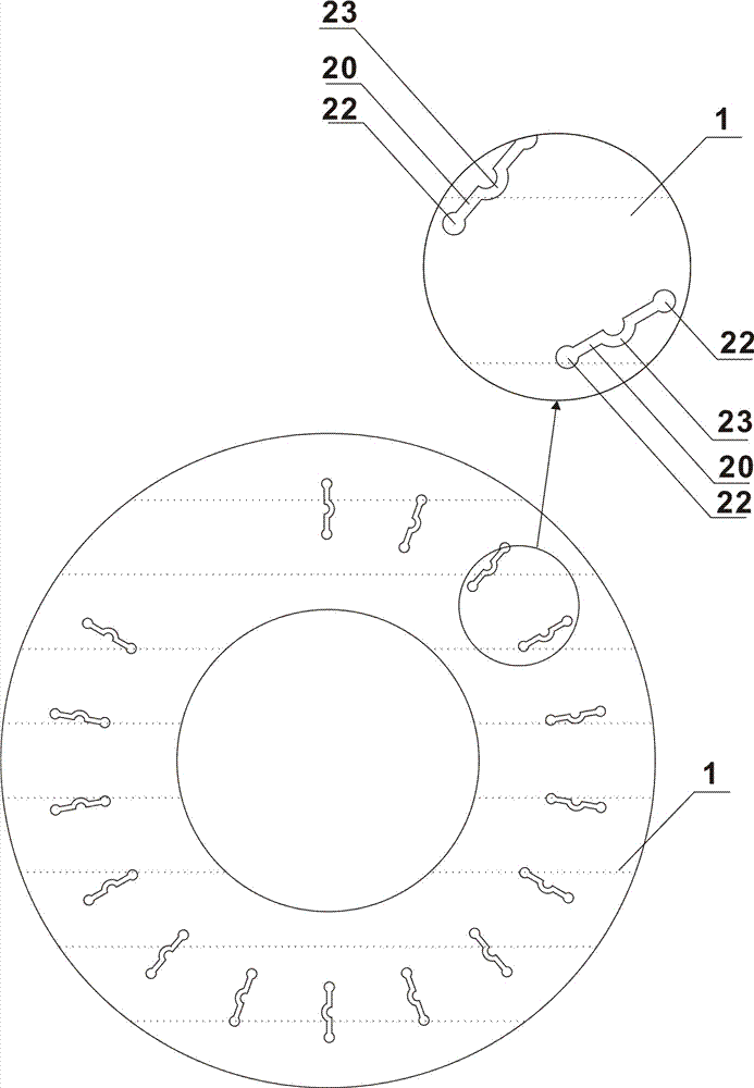
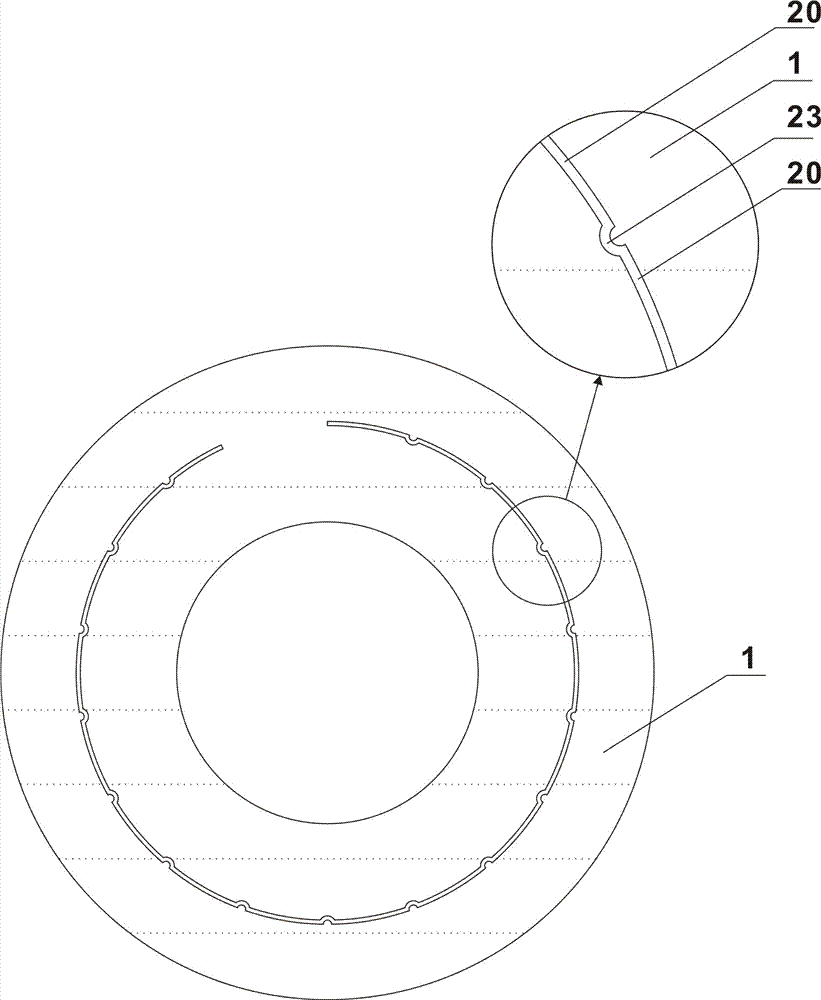
[0049] refer to Figure 1 ~ Figure 2 , the present invention is a speed regulating groove part, comprising a body 1, the speed regulating groove 2 with different apertures is arranged on the body 1, a groove body 20 is arranged on the speed regulating groove 2, and the speed regulating groove 2 is provided with a groove body 20. The groove 2 is also provided with a dislocation segment 23 with a different plane and / or a different center and / or a different angle and / or a different tangent plane from the groove body 20 .

[0050]As a preferred embodiment of the present invention, the body 1 is hollow cylindrical, the speed regulating groove 2 is arranged on the inner side wall of the body 1, the speed regulating groove 2 is provided with a groove body 20, and the speed regulating groove 2 2 is also provided with a dislocation section 23 that is different from the plane of the tank body 20; or the upper surface of the body 1 is a plane, and the speed regulating groove 2 is arrange...


PUM


Abstract

The invention discloses a speed-regulating groove component which comprises a body, wherein speed-regulating grooves of different pore sizes are formed in the body; a tank body is arranged on the speed-regulating grooves; and dislocation sections in different planes and/or different circle centers and/or different angles and/or different sections with the tank body are arranged on the speed-regulating grooves. According to the dislocation sections, a support on a sealing gasket can be formed, the possibility of enabling the sealing gasket to protrude into the speed-regulating groove with deformation can be reduced, and the influence of the protrusion of the sealing gasket into the speed-regulating groove with deformation on the actual liquid flow passing cross sectional area of the speed-regulating groove is further reduced. According to a non-contact processing manner, the process influence in the injection molding process can be reduced, the cutting and punching precision can be ensured on most of the materials, and stable quality is maintained. The speed-regulating groove component disclosed by the invention is applied to the fields of medical equipment fittings and medical equipment.

Description

technical field [0001] The invention relates to the field of medical device accessories and medical devices, in particular to a component as a speed regulating groove. Background technique [0002] At present, the speed-regulating parts in the infusion regulator are provided with one or more speed-regulating grooves, which are equipped with speed-regulating grooves with continuously changing cross-sectional areas; or are equipped with segmental speed-regulating grooves with different cross-sectional areas. Because clinical infusion requires high speed regulation accuracy of the infusion regulator, and the speed regulation accuracy often depends on the accuracy of the cross-sectional area of ​​the speed regulation groove, especially in fine flow speed regulation, the cross-sectional area of ​​the speed regulation groove is greater than or equal to µm 2 as a unit of measurement. [0003] Most of the speed regulating grooves adopt open groove design. In order to avoid uneven ...

Claims


Application Information

Patent Timeline
Patent Type & Authority Applications(China)
IPC IPC(8): A61M5/168
CPCA61M5/16813A61M5/16877A61M2205/3331A61M2207/00
Inventor 汤丽芬胡绍勤
Owner GUANGZHOU JIANZHITANG MEDICAL INSTR CO LTD
Why Eureka
Try Eureka