
Control system for high exhaust vent valve of megawatts unit turbine

A control system, a technology of millions of units, applied in valve details, valve devices, mechanical equipment, etc., can solve the problems of loose air pipe joints, solenoid valve coil burnout, and high temperature, so as to reduce the probability of burnout and reduce failures. , The effect of reliable and safe operation

Active Publication Date: 2017-12-12
广东粤电靖海发电有限公司
View PDF5 Cites 0 Cited by
  • Summary
  • Abstract
  • Description
  • Claims
  • Application Information

AI Technical Summary

Problems solved by technology

[0003] When the unit is running normally, especially at full load, the main steam pressure is as high as 25.4MPa, and the working environment where the VV valve is located is high in temperature and vibration, which may easily lead to breakage of the gas line system, loose joints of the gas line pipes, and limit switches of the feedback device. Faults such as looseness and loose wiring of the feedback device; at the same time, the solenoid valve of the VV valve is in a long-term charged state, and the probability of the solenoid valve coil burning out is also greatly increased.
The above failures may cause the VV valve to open due to failure during the normal operation of the unit. The abnormal opening of the VV valve will cause the high-pressure steam to be directly discharged to the condenser. The high-temperature and high-pressure steam will directly wash the titanium tube of the condenser, which will cause damage to the titanium tube. Seriously affect the safe and stable operation of the unit, so the correct and stable work of the VV valve is particularly important

Method used


Image

  • Control system for high exhaust vent valve of megawatts unit turbine
  • Control system for high exhaust vent valve of megawatts unit turbine
  • Control system for high exhaust vent valve of megawatts unit turbine

Examples


Embodiment Construction

[0031] The present invention is further described below in conjunction with embodiment.

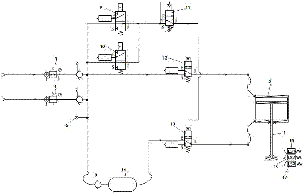
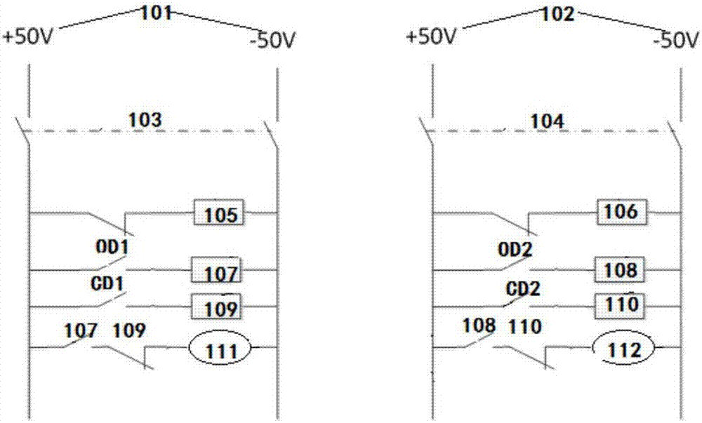
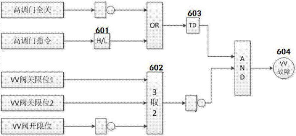
[0032] The embodiment of the high exhaust ventilation valve control system of a steam turbine with a million units of the present invention includes a pneumatic pipeline, a double-acting cylinder 2, two control circuits and a high exhaust ventilation valve fault diagnosis device.

[0033] Such as figure 1 Schematic diagram of the assembly of the pneumatic lines and double-acting cylinder shown. The telescopic rod 1 of the double-acting cylinder 2 is connected to the spool of the high-discharge ventilation valve, and the closing and opening of the high-discharge ventilation valve is completed by extending and retracting the telescopic rod. The pneumatic pipeline includes two independent and identically configured intake pipelines, a first execution pipeline, a second execution pipeline and a control pipeline. The air intake pipeline is provided with first and second filter decompressors ...


PUM


Abstract

The invention discloses a control system for a high exhaust vent valve of a megawatts unit turbine. The control system comprises a pneumatic pipeline and a double-acting air cylinder. A telescopic rod of the double-acting air cylinder is connected with a valve core of the high exhaust vent valve. Opening and closing of the high exhaust vent valve are completed through extending and contracting of the telescopic rod. The pneumatic pipeline comprises an air inlet pipeline, a first operating pipeline, a second operating pipeline and a control pipeline. The air inlet ends of the first operating pipeline, the second operating pipeline and the control pipeline are correspondingly connected with the air outlet end of the air inlet pipeline. Extending and contracting of the double-acting air cylinder are controlled through the first operating pipeline and the second operating pipeline. Connecting and disconnecting of air of the first operating pipeline and the second operating pipeline are controlled by the control pipelines. A control part of the control system for the high exhaust vent valve of the megawatts unit turbine can keep a distance from a turbine unit, malfunction is reduced, and running is more reliable and safer.

Description

technical field [0001] The invention relates to a control system for a high-discharge ventilation valve, in particular to a control system for a high-discharge ventilation valve of a steam turbine with millions of units. Background technique [0002] The high exhaust ventilation valve (referred to as VV valve) is mainly equipped on the steam turbine unit produced by Dongfang Steam Turbine Factory. The valve is installed in the exhaust pipe section of the high pressure cylinder and is connected with the condenser to maintain the vacuum of the unit. There are two main functions of the VV valve: one is to open the VV valve after the pre-heating of the high-pressure cylinder to release the steam pressure between the high-pressure regulating door and the central joint door; the other is to quickly open the VV valve when the unit trips or dumps Steam from the high-pressure cylinder prevents damage to the equipment due to overheating of the high-pressure rotor blades due to overhea...

Claims


Application Information

Patent Timeline
Patent Type & Authority Applications(China)
IPC IPC(8): F16K31/122F16K31/06F16K37/00F15B13/044F15B13/02
CPCF15B13/02F15B13/044F16K31/0675F16K31/122F16K37/0025F15B2013/0448
Inventor 瞿七九刘锋粟宣淞何善鸿唐田刘艳冬孙晓锋
Owner 广东粤电靖海发电有限公司
Learn More