VCOM voltage adjusting circuit with controllable range and method thereof
A voltage regulation circuit and range technology, used in instruments, static indicators, etc., can solve the problems of large VCOM adjustable range, low accuracy, slow efficiency, etc., and achieve the effect of controllable adjustment range and improved adjustment accuracy.
- Summary
- Abstract
- Description
- Claims
- Application Information
AI Technical Summary
Problems solved by technology
Method used
Image

Examples
Embodiment 1
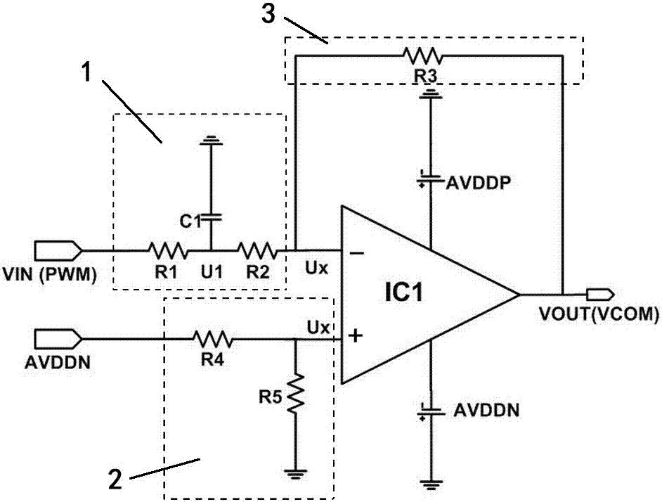
[0027] A range-controllable VCOM voltage regulation circuit includes an operational amplifier unit IC1 , a positive input circuit 1 , a negative input circuit 2 and a feedback circuit 3 .
[0028] Wherein, the negative input circuit 2 is connected to the bottom input terminal of the operational amplifier unit IC1, receives the PWM signal source, and adjusts the maximum and minimum values of the input voltage according to the duty cycle of the PWM signal source.
[0029] The positive input circuit 1 is connected to the positive input terminal of the operational amplifier unit IC1 to provide a reference voltage signal for the operational amplifier unit IC1, and the input terminal of the positive input circuit 1 is connected to the negative AVDD terminal. In this embodiment, AVDD refers to an analog voltage source.
[0030] The feedback circuit 3 is a negative feedback circuit 3, which cooperates with the negative input circuit 2 to adjust the specific values of the maximum v...
Embodiment 2
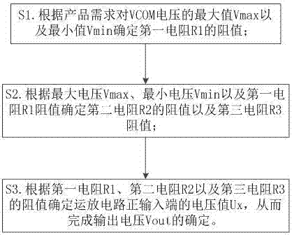
[0043] This embodiment provides a VCOM voltage regulation method on the basis of Embodiment 1, specifically including:
[0044] S1. Determine the resistance value of the first resistor R1 for the maximum value Vmax and the minimum value Vmin of the VCOM voltage according to product requirements;
[0045] S2. Determine the resistance value of the second resistor R2 and the resistance value of the third resistor R3 according to the maximum voltage Vmax, the minimum voltage Vmin, and the resistance value of the first resistor R1;
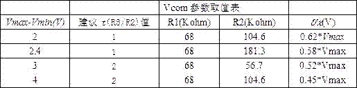
[0046] S3. Determine the voltage value Ux of the positive input terminal of the operational amplifier circuit according to the resistance values of the first resistor R1, the second resistor R2 and the third resistor R3, thereby completing the determination of the output voltage Uout. Usually, Ux can be determined when the ratio t of the third resistor R3 to the second resistor R2 is determined.
[0047] The following table shows the recommended val...
PUM
 Abstract
Description
Claims
Application Information
 - Generate Ideas
- Intellectual Property
- Life Sciences
- Materials
- Tech Scout
- Unparalleled Data Quality
- Higher Quality Content
- 60% Fewer Hallucinations
Browse by: Latest US Patents, China's latest patents, Technical Efficacy Thesaurus, Application Domain, Technology Topic, Popular Technical Reports.
© 2025 PatSnap. All rights reserved.Legal|Privacy policy|Modern Slavery Act Transparency Statement|Sitemap|About US| Contact US: help@patsnap.com