Pyramid annular resonant cavity

A ring resonator and pyramid technology, applied in the field of resonators, can solve the problems of poor beam quality, loss of output, no output, etc.

Inactive Publication Date: 2017-12-12
北京思通博远激光科技有限公司
View PDF1 Cites 2 Cited by
  • Summary
  • Abstract
  • Description
  • Claims
  • Application Information

AI Technical Summary

Problems solved by technology

[0005] The relative positional relationship between the two flat mirrors and the two concave mirrors in the existing document 1 is strictly limited. Once one or several cavity mirrors are deflected when the cavity vibrates, the light beam will deviate from the cavity during circular operation. , resulting in poor quality or even no output beam output from the resonator, and in harsh environments, such as vehicle, military, etc., the cavity of the resonator often vibrates. The preset output will be lost for a short time due to the angular position deviation of the cavity mirror

Method used


Image

  • Pyramid annular resonant cavity
  • Pyramid annular resonant cavity
  • Pyramid annular resonant cavity

Examples


Embodiment 1

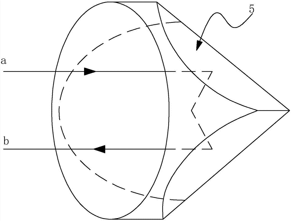
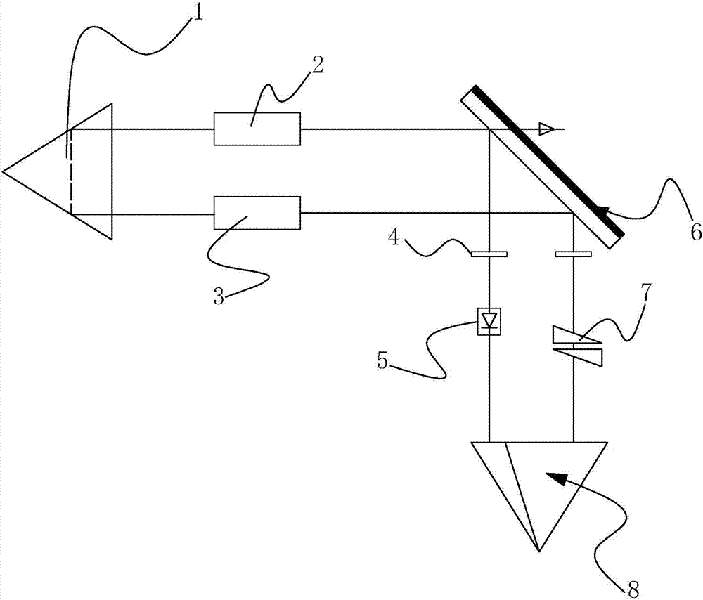
[0038] A pyramidal ring resonator, such as Figures 1 to 2 As shown, it includes a cavity and optical devices arranged in the cavity. The optical devices in the cavity include a translation retroreflective device 1, a nonlinear crystal 2, a laser material 3, a half-wave plate 4, a one-way operation control device 5, a cavity mirror 6 arranged obliquely, and a corner cube prism 8, wherein the translation The function of the retroreflection device 1 is to translate the incident light into the retroreflection. Therefore, it can be a right-angle prism, a corner cube prism, or two high-reflection mirrors fixed at right angles to each other. When installing, the apex of the right-angle prism needs to be , or the vertex of the corner cube prism or the intersection line of two mutually fixed high-reflection mirrors is set opposite to the corner of the corner cube prism 8 . The arrangement angle of the cavity mirror 6 can meet the reflection requirement between 0° and 90°, and the pre...

Embodiment 2

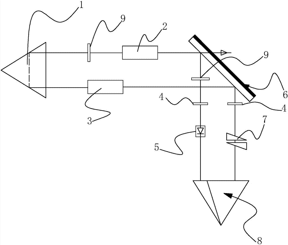
[0045] Such as image 3 As shown in , two convex mirrors 9 are added at both ends of the nonlinear crystal 2 to reduce the spot area of ​​the beam on the nonlinear crystal 2, so that the incident beam of the nonlinear crystal 2 is more concentrated, thereby ensuring the output in the ring cavity the quality of the laser beam. Other settings in this embodiment are kept the same as those in Embodiment 1.

Embodiment 3

[0047] Such as Figure 4 As shown in , the pumping form in Embodiment 2 is limited to side pumping 0 to reduce the thermal effect of the active laser material 3 and the manufacturing cost of the overall ring cavity. All the other settings are the same as in Example 3.


PUM


Abstract

The invention discloses a pyramid ring resonant cavity, which solves the technical problem that the traveling wave cavity in the prior art requires extremely precise installation angle of the cavity mirror and is not suitable for use in harsh environments. The main points of the technical solution are It includes a cavity and an active laser material arranged in the cavity, a corner cube prism and a one-way operation control device. The cavity also includes a high reflection mirror for reflecting the fundamental frequency light, a frequency modulation light output, and a fundamental frequency light reflection device. Cavity mirror, nonlinear crystal and right-angle prism, the beam emitted by the active laser material under the excitation of external pump enters the right-angle prism vertically and reflects out in parallel, and the beam enters the nonlinear crystal and enters the cavity mirror at an angle of 45 degrees and reflects Entering the one-way operation control device, the outgoing light returns to the active laser material after being reflected by the corner cube prism. Through the adjustment of the components in the cavity, the requirements for the installation accuracy of each component in the wall are reduced, so that the resonant cavity can meet the use in harsh environments.

Description

technical field [0001] The invention relates to a resonant cavity, in particular to a pyramid ring resonant cavity capable of realizing high-power frequency modulation output in the cavity. Background technique [0002] The function of the resonant cavity is to amplify the light of the same frequency and direction in the laser material, and suppress the light of other frequencies and directions. The back-and-forth motion produces oscillations, causing other excited particles in the laser material to meet with it to generate radiation, and the photons running along the axis will continue to proliferate, forming a strong beam with the same propagation direction, the same frequency and phase in the cavity, and generating laser light. [0003] The resonant cavity is divided into two types in terms of the circulation of the beam inside the cavity: traveling wave cavity (also called ring cavity) and standing wave cavity. To go, multiple light waves with similar wavelengths are re...

Claims


Application Information

Patent Timeline
Patent Type & Authority Applications(China)
IPC IPC(8): H01S3/083
CPCH01S3/083
Inventor 李永明刘练王晨马东伟刘少飞宋宝钢
Owner 北京思通博远激光科技有限公司
Why Eureka
Try Eureka