Oil-water separator for compressed air and heatless regeneration type compressed air dryer

An oil-water separator and compressed air technology, applied in separation methods, dispersed particle separation, gas treatment, etc., can solve the problems of increased maintenance workload, wear of pneumatic equipment, complex structure, etc., and achieve simple structure, cost reduction, and drying effect. Good results

Pending Publication Date: 2017-12-15
ZHUZHOU LINCE GRP
View PDF5 Cites 6 Cited by
  • Summary
  • Abstract
  • Description
  • Claims
  • Application Information

AI Technical Summary

Problems solved by technology

[0002] The compressed air of the braking system of locomotives and trains usually contains impurities such as water, oil, and dust. The water, oil, and dust of locomotives and trains usually cause corrosion and freezing, resulting in failures and accelerated wear of pneumatic equipment. Therefore, locomotives generally use Compressed air dryers purify compressed air, and compressed air dryers generally use oil-water separators for auxiliary purification. Most of the oil-water separators used in existing compressed air dryers have complex structures. On the one hand, it increases the maintenance workload. High cost on the one hand

Method used


Image

  • Oil-water separator for compressed air and heatless regeneration type compressed air dryer
  • Oil-water separator for compressed air and heatless regeneration type compressed air dryer
  • Oil-water separator for compressed air and heatless regeneration type compressed air dryer

Examples


Embodiment Construction

[0032] The embodiments of the present invention will be described in detail below with reference to the accompanying drawings, but the present invention can be implemented in various ways defined and covered by the claims.

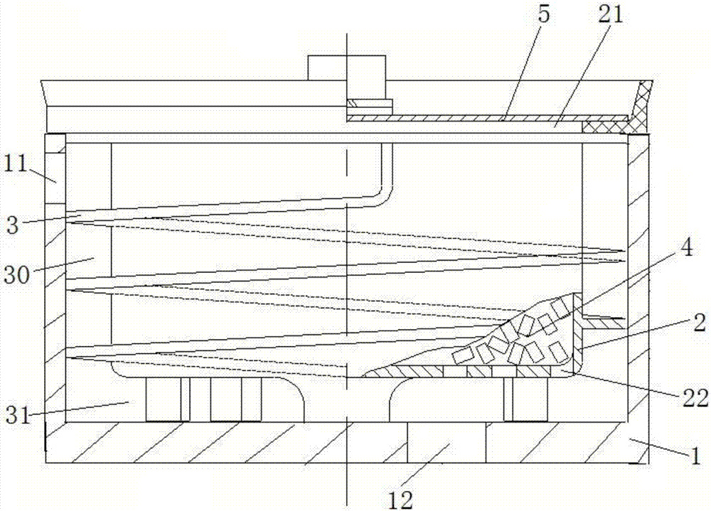
[0033] see figure 1 The oil-water separator for compressed air includes an outer shell 1 and an inner shell 2. The outer shell is arranged on the periphery of the inner shell, and the height of the outer bottom surface of the inner shell is higher than the inner bottom surface of the outer shell. The gas enters or exits the entrance 21 and the entrance 2 22. A guide bar 3 in a spiral structure is arranged between the inner wall of the outer shell and the outer wall of the inner shell. The guide bar 3 of the spiral structure forms a spiral between the outer shell and the inner shell. The upper part of the outer casing is provided with a connection port 11, one end of the connection port 1 is used to directly or indirectly connect compressed air, the other e...


PUM


Abstract

The invention provides an oil-water separator for compressed air. The oil-water separator comprises an outer shell (1) and an inner shell (2), wherein the outer shell is arranged at the periphery of the inner shell; a guiding bar (3) which is of a spiral structure is arranged between the inner wall of the outer shell and the outer wall of the inner shell; a spiral gas guiding passage (30) is formed between the outer shell and the inner shell by the guiding bar which is of the spiral structure; the inner part of the inner shell is filled with filter filler (4) for filtering oil, water and impurities. According to the oil-water separator for the compressed air, provided by the invention, flow guiding is carried out on the compressed air by utilizing the spiral gas guiding passage arranged between the outer shell and the inner shell, the structure is simple, and the drying effect is good. In a heatless regeneration type compressed air dryer provided by the invention, the oil-water separator is arranged in a drying tower; the oil-water separation effect is good, the maintenance is convenient, and the cost is greatly reduced; the outer surface of a control valve is coated with a PTC (Positive Temperature Coefficient) heating plate by the heatless generation type compressed air dryer, so that the function of maintaining constant power is obtained, and the safety performance is good.

Description

technical field [0001] The invention relates to the field of air sources for braking systems of locomotives and motor vehicles, and in particular to an oil-water separator for compressed air and a heatless regenerative compressed air dryer. Background technique [0002] The compressed air of the braking system of locomotives and trains usually contains impurities such as water, oil, and dust. The water, oil, and dust of locomotives and trains usually cause corrosion and freezing, resulting in failures and accelerated wear of pneumatic equipment. Therefore, locomotives generally use Compressed air dryers purify compressed air, and compressed air dryers generally use oil-water separators for auxiliary purification. Most of the oil-water separators used in existing compressed air dryers have complex structures. On the one hand, it increases the maintenance workload. On the one hand, the cost is high. Therefore, in the prior art, there is a need for an oil-water separator with ...

Claims


Application Information

Patent Timeline
Patent Type & Authority Applications(China)
IPC IPC(8): B01D50/00B01D53/26
CPCB01D53/26B01D2257/80B01D50/20
Inventor 钟永强易锡
Owner ZHUZHOU LINCE GRP
Why Eureka
Try Eureka