Thruster flow passage structure, thruster and underwater vehicle

A propeller and flow channel technology, which is applied in the direction of ship propulsion, propulsion parts, ship parts, etc., can solve the problems of propeller thrust reduction, improvement, and unfavorable propulsion efficiency of propellers, so as to improve propulsion efficiency, reduce influence, and increase propulsion efficiency. The effect of high thrust

Pending Publication Date: 2017-12-15
POWERVISION TECH
View PDF5 Cites 4 Cited by
  • Summary
  • Abstract
  • Description
  • Claims
  • Application Information

AI Technical Summary

Problems solved by technology

[0003] The purpose of the present invention is to provide a propeller channel structure, a propeller and an underwater vehicle to solve the problem that the propeller of an underwater vehicle in the prior art is propelled, and the underwater flow field is easy to make the propeller The thrust generated by the propeller becomes smaller, which is not conducive to the technical problem of improving the propulsion efficiency of the propeller

Method used


Image

  • Thruster flow passage structure, thruster and underwater vehicle
  • Thruster flow passage structure, thruster and underwater vehicle
  • Thruster flow passage structure, thruster and underwater vehicle

Examples


Embodiment 1

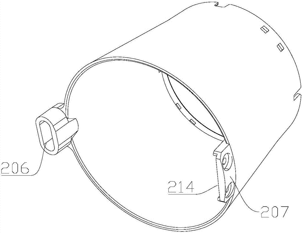
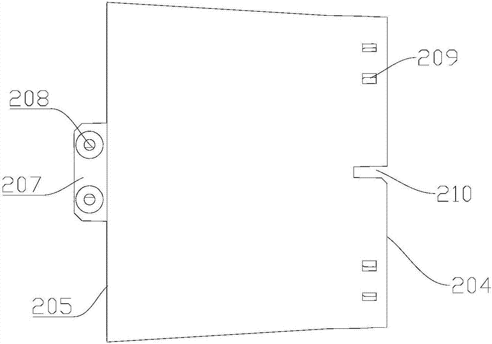
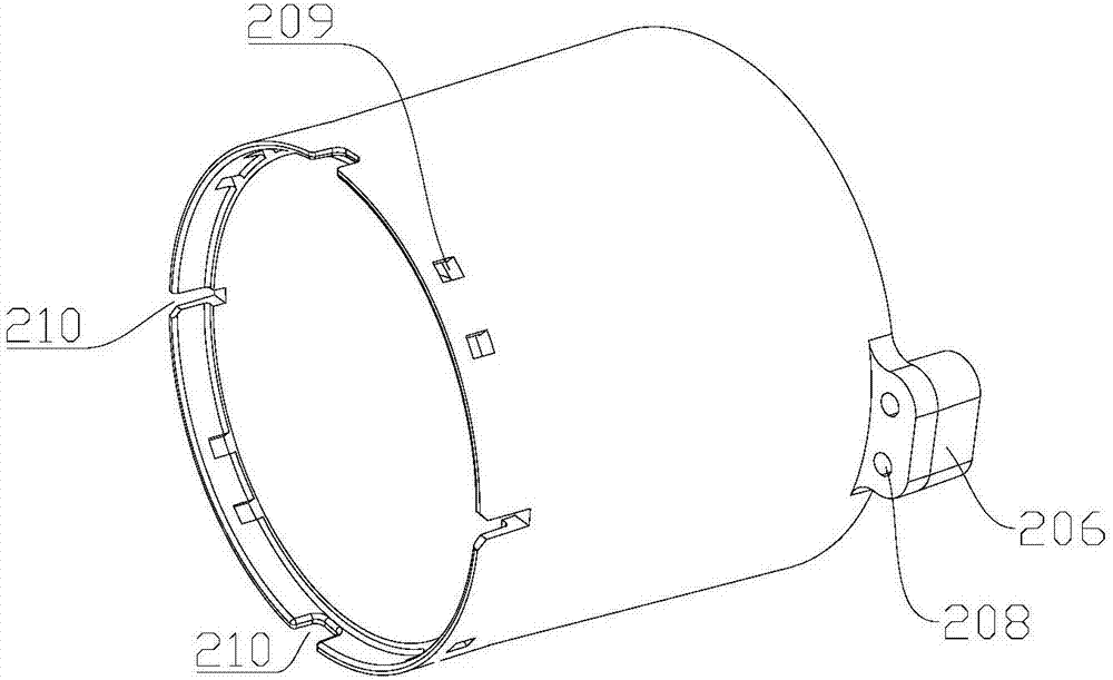
[0038] See Figure 1 to Figure 4 As shown, the first embodiment of the present invention provides a propeller flow channel structure, including a draft tube 203, the draft tube 203 has a front end 204 and a rear end 205 opposite, the radial cross section of the draft tube 203 is circular ; Along the axial direction of the draft tube 203, the outer diameter of the draft tube 203 gradually decreases from the rear end 205 to the front end 204; along the axial direction of the draft tube 203, the inner diameter of the draft tube 203 from the rear end 205 to The front end 204 first gradually decreases to the first set value, and then gradually increases from the first set value.

[0039] Specifically, the radial cross section of the draft tube 203 is a torus, and the projection of the axial cross section of the draft tube 203 on the reference plane has a trapezoidal outer profile, which ensures that the draft tube 203 has a very standardized fixed size , Reducing the processing diffic...

Embodiment 2

[0050] See Figure 5 to Figure 11 As shown, the second embodiment of the present invention provides a propeller, including a power unit 201, a propeller 202, and a propeller flow channel structure; the draft tube 203 is fixedly connected to the casing 211 of the power unit 201, and the power unit 201 is used for driving The propeller 202 rotates.

[0051] In an optional solution of this embodiment, the propeller further includes a stator blade structure, and the stator blade structure is fixedly connected to the flow channel structure of the propeller, that is, the stator blade structure is fixedly connected to the draft tube 203.

[0052] In an optional solution of this embodiment, the stator blade structure includes a mounting ring 101 and a plurality of stationary blades 102; the plurality of stationary blades 102 are fixedly connected to the inner wall of the mounting ring 101, and the plurality of stationary blades 102 are distributed radially, wherein the stationary blades O...

Embodiment 3

[0062] The embodiment of the present invention provides an underwater vehicle, including the propeller provided in the second embodiment and the aircraft fuselage. The propeller can be installed on the tail of the aircraft fuselage, on the head of the aircraft fuselage, or on both sides of the aircraft fuselage.


PUM


Abstract

The invention relates to the technical field of underwater navigation equipment, in particular to a thruster flow passage structure, a thruster and an underwater vehicle. The thruster flow passage structure comprises a flow guide pipe, and the flow guide pipe is provided with a front end and a rear end which are opposite to each other. The radial cross section of the flow guide pipe is in a circular ring shape. The outer diameter of the flow guide pipe decreases gradually from the rear end to the front end in the axial direction of the flow guide pipe. The inner diameter of the flow guide pipe firstly gradually decreases to a first set value, and then increases gradually from the first set value from the rear end to the front end in the axial direction of the flow guide pipe. The thruster comprises a power device, a propeller and the thruster flow passage structure. The flow guide pipe is fixedly connected with a shell of the power device, and the power device is used for driving the propeller to rotate. The underwater vehicle comprises the thruster. The thruster flow passage structure, the thruster and the underwater vehicle improve the working efficiency of the propeller to water, facilitate improvement of the thrusting efficiency of the thruster, and increase the thrust.

Description

Technical field [0001] The invention relates to the technical field of underwater navigation equipment, in particular to a propeller flow channel structure, a propeller and an underwater vehicle. Background technique [0002] When the propeller of the underwater vehicle in the prior art is propelled, the underwater flow field tends to reduce the thrust generated by the propeller of the propeller, which is not conducive to the improvement of the propulsion efficiency of the propeller. Summary of the invention [0003] The purpose of the present invention is to provide a propeller channel structure, a propeller and an underwater vehicle to solve the problem that the underwater flow field of the underwater vehicle in the prior art will easily cause the propeller to be propelled. The thrust generated by the propeller becomes smaller, which is not conducive to the technical problem of improving the propulsion efficiency of the propeller. [0004] The present invention provides a flow ch...

Claims


Application Information

Patent Timeline
Patent Type & Authority Applications(China)
IPC IPC(8): B63H5/15
CPCB63H5/15
Inventor 不公告发明人
Owner POWERVISION TECH
Why Eureka
Try Eureka