Elevator safety clamp device
A technology of safety gear and elevators, applied in the field of elevators, can solve problems such as unsafe accidents, long response time, and complex structure, and achieve the effects of good synchronization, short response time, and small size
- Summary
- Abstract
- Description
- Claims
- Application Information
AI Technical Summary
Problems solved by technology
Method used
Image
Examples
Embodiment 1
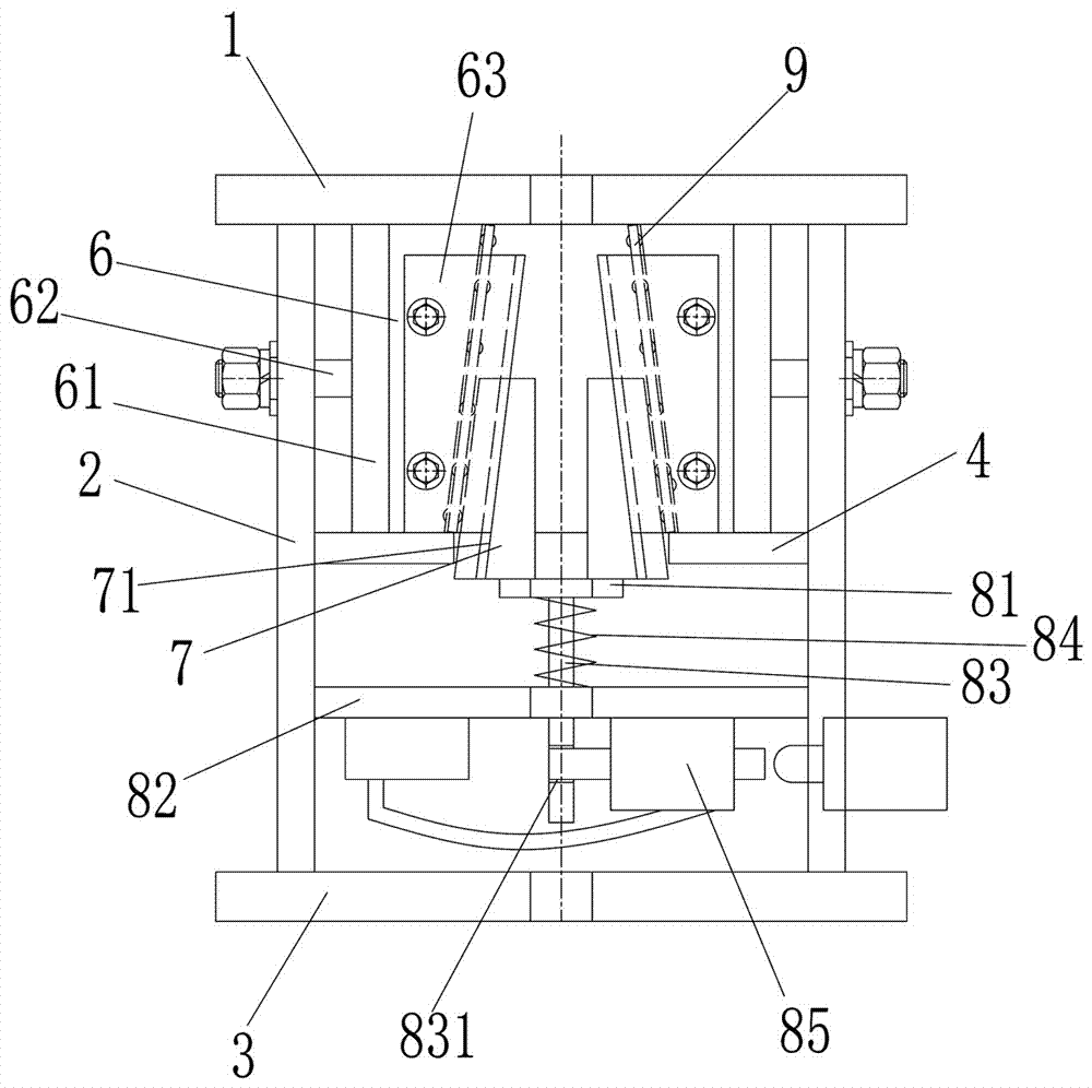
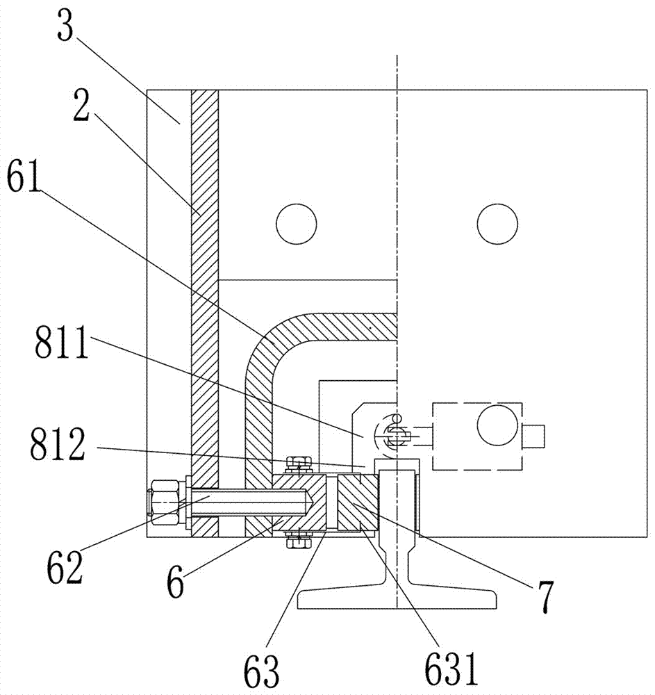
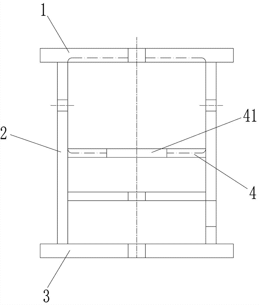
[0037] An elevator safety gear device, comprising a clamp body and a wedge assembly arranged in the clamp body, the clamp body includes a top plate 1, two side plates 2, a bottom plate 3, and a middle guide plate 4 arranged in sequence from top to bottom. The upper and lower ends of the side plates are respectively fixedly connected with the top plate and the bottom plate, and the front sides of the top plate, the bottom plate, and the middle guide plate are respectively provided with guide rail passages 5 for passing the elevator guide rails, and the middle guide plate is arranged on the two sides. The part between the two side plates and corresponding to the guide rail channel is provided with a guide opening 41 with a diameter larger than that of the guide rail channel; the wedges include two horizontal wedges 6 and two symmetrically arranged on both sides of the guide rail channel. The upper and lower wedges 7, the upper and lower ends of the horizontal wedges are against t...
Embodiment 2
[0045] The difference from the above-mentioned embodiments is that the main board part is provided with thickened parts 813 at least corresponding to the bottoms on both sides of the two sub-board parts, and the sub-board part and the thickened parts are integrally connected by triangular ribs , the support plate is provided with a secondary hole corresponding to the secondary plate portion, and the bottom of the secondary plate portion is provided with a secondary guide rod 8121 penetrating in the secondary hole.
[0046] The upper and lower wedges are set on the sub-board part, so as to free up space to form a slot through the guide rail. In this application, through the setting of the above-mentioned sub-guide rod, it cooperates with the guide rod to form a stable guiding result, so as to ensure that it is suspended from the main board. When the external sub-plate is under force, it can also stably lift the upper and lower wedges without being prone to deflection or jamming,...
Embodiment 3
[0048] The difference from the above-mentioned embodiment is that the bottom of the top plate is also provided with a reset part for making the upper and lower wedges reset downward, and the reset part includes at least two push plates 101 above the upper and lower wedges at least on both sides, solid A push rod 102 connected to the center of symmetry on the upper surface of the push plate, a push spring 103 sleeved on the push rod, an insertion rod 104 inserted into the push rod from the side, and an electromagnet for controlling the expansion and contraction of the insertion rod 105, the top plate is provided with a reset frame, the push plate is located below the top plate, the push rod passes through the top plate, and the push spring is arranged on the top plate and the top frame plate of the reset frame 106; a baffle 31 for limiting the position of the guide rod is provided under the support plate, and a touch switch is provided on the baffle.
[0049] Through the settin...
PUM
 Abstract
Description
Claims
Application Information
 - R&D
- Intellectual Property
- Life Sciences
- Materials
- Tech Scout
- Unparalleled Data Quality
- Higher Quality Content
- 60% Fewer Hallucinations
Browse by: Latest US Patents, China's latest patents, Technical Efficacy Thesaurus, Application Domain, Technology Topic, Popular Technical Reports.
© 2025 PatSnap. All rights reserved.Legal|Privacy policy|Modern Slavery Act Transparency Statement|Sitemap|About US| Contact US: help@patsnap.com


