A kind of mechanical compact spinning method
A mechanical, compact spinning technology, applied in spinning machines, textiles and papermaking, drafting equipment, etc., can solve the problem of restricting the high energy consumption of compact spinning, and achieve the effects of reducing energy consumption, saving production costs, and high strength
- Summary
- Abstract
- Description
- Claims
- Application Information
AI Technical Summary
Problems solved by technology
Method used
Image
Examples
Embodiment 1
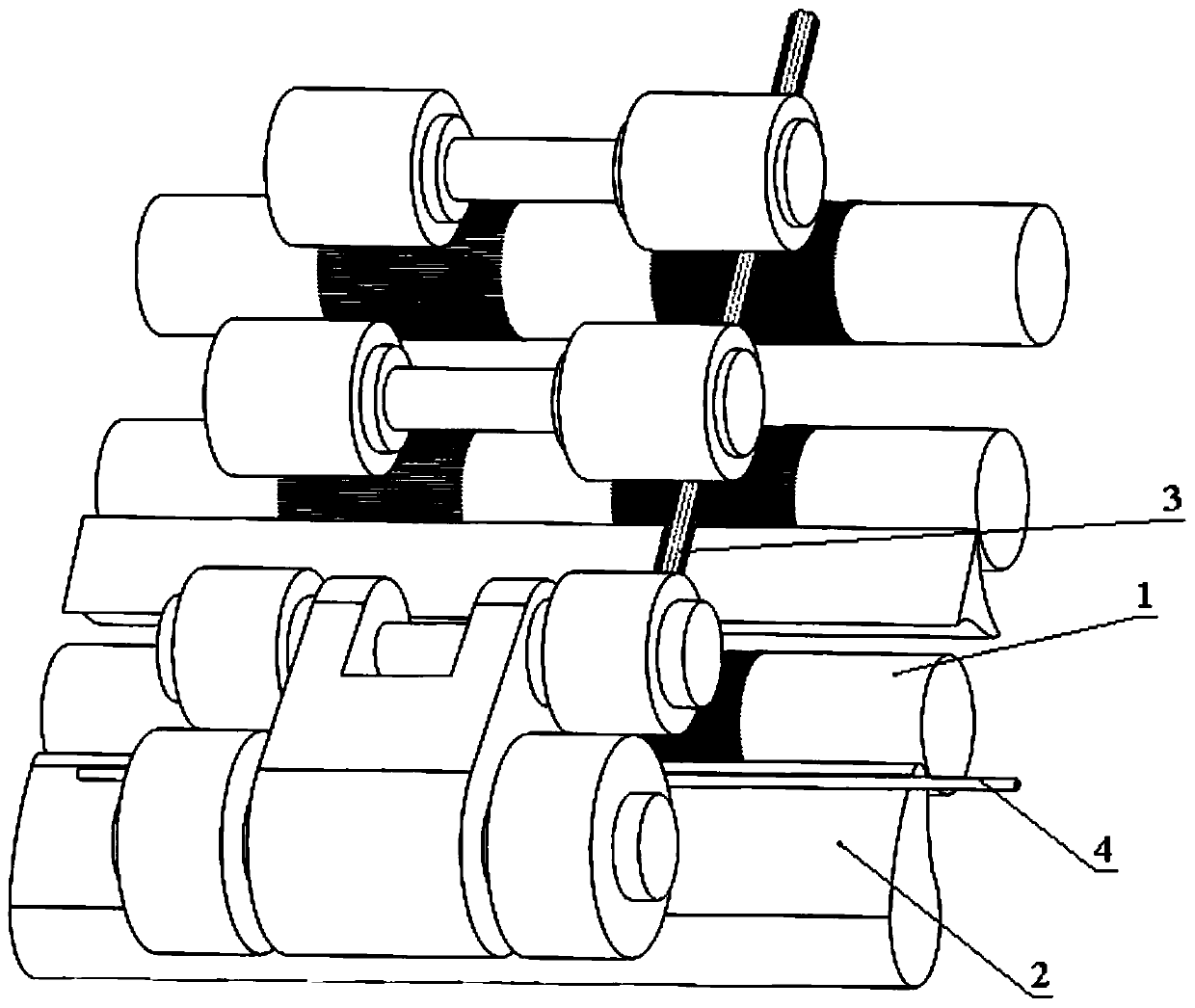
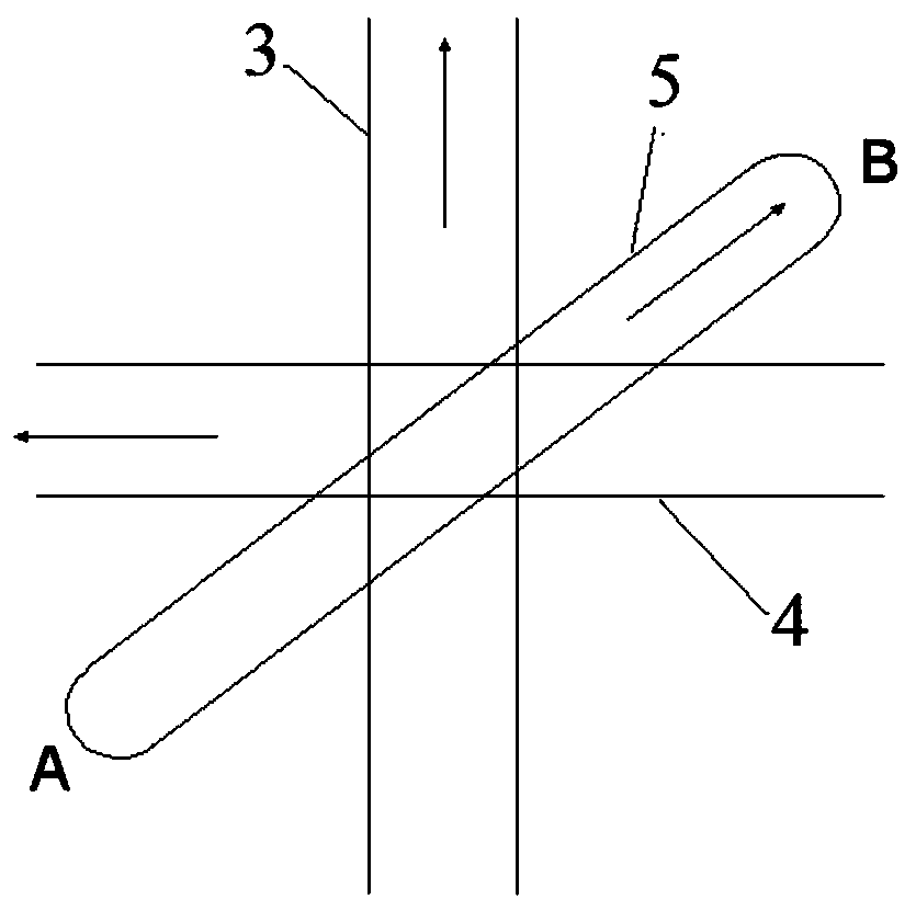
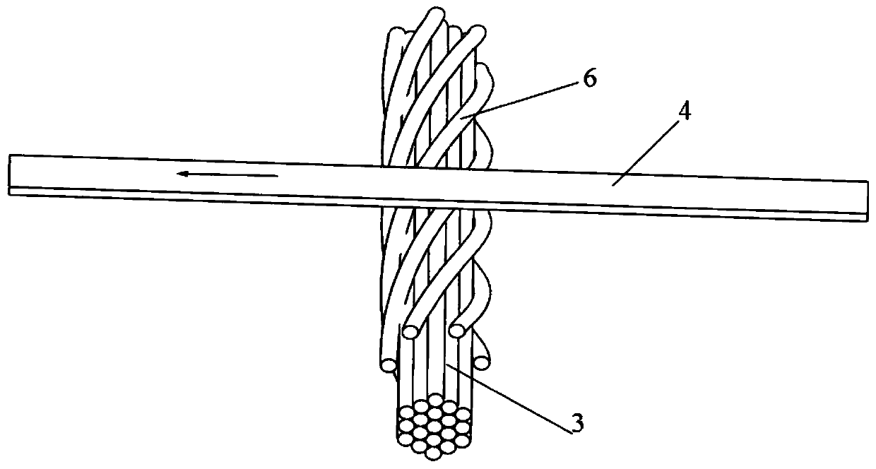
[0029] A mechanical compact spinning method such as figure 1 As shown, a friction device 4, namely a belt, is set above the sliver 3 in the accumulation area between the output nip of the front roller 1 of the compact spinning ring spinning machine and the twisting triangle area. The friction part on the surface of the belt is perpendicular to the surface of the sliver, and the , the relative positions of the gathering groove 5 and the sliver 3 are as figure 2 As shown, the belt moving direction and the running direction of the yarn 3 are at an angle of 90°, the angle between the slotting direction of the gathering groove 5 and the running direction of the yarn 3 is 10°, and the slotting direction of the gathering groove 5 is located at the direction of the belt moving. Between the opposite direction and the running direction of the sliver 3, the slotting direction of the accumulation groove 5 is the direction in which the accumulation groove 5 extends from the groove end A t...
Embodiment 2
[0033] A mechanical compact spinning method such as figure 1 As shown, a friction device 4, namely a brush 7, is set above the sliver 3 in the accumulation area between the output nip of the front roller 1 of the compact spinning ring spinning frame and the twisting triangle area, and the brush 7 is as follows: Figure 4 As shown, the friction part is fine hair 8, and the density of fine hair 8 is 500 / cm 2 , the fineness of the fine hair 8 is 0.05mm, the length of the fine hair 8 is 5mm, the fine hair 8 is perpendicular to the sliver surface, and the relative positions of the hairbrush 7, the accumulation groove 5 and the sliver 3 are as follows figure 2 As shown, the moving direction of the brush 7 is at an angle of 90° to the running direction of the yarn sliver 3, the angle between the grooved direction of the accumulation groove 5 and the running direction of the yarn 3 is 20°, and the grooved direction of the accumulation groove 5 is located at the position of the brush ...
Embodiment 3
[0037] A mechanical compact spinning method, the structure and method of which are the same as in Example 1, the difference lies in some of its process parameters: the angle between the slotting direction of the compacting groove and the running direction of the sliver is 30°, and the diameter of the belt is 3mm , the distance between the friction parts on the belt surface and the grid ring is 1mm, the thickness of the sliver is 1.08mm, the belt running speed is 0.5m / min, the pressure of the negative pressure airflow in the accumulation groove is -1000Pa, the sliver count It is 10 pounds, the spindle speed is 4000rpm, the twist is 400 twists / m, and the roving weight is 5g / 10m.
[0038] The evenness CV% value of the yarn finally obtained was 9.67, the number of -40% fine places was 0 / km, the number of +35% thick places was 50 / km, the breaking strength was 17.31cN / tex, and the breaking elongation The rate is 9.73%.
PUM
| Property | Measurement | Unit |
|---|---|---|
| Diameter | aaaaa | aaaaa |
| Width | aaaaa | aaaaa |
| Fineness | aaaaa | aaaaa |
Abstract
Description
Claims
Application Information
 - R&D
- Intellectual Property
- Life Sciences
- Materials
- Tech Scout
- Unparalleled Data Quality
- Higher Quality Content
- 60% Fewer Hallucinations
Browse by: Latest US Patents, China's latest patents, Technical Efficacy Thesaurus, Application Domain, Technology Topic, Popular Technical Reports.
© 2025 PatSnap. All rights reserved.Legal|Privacy policy|Modern Slavery Act Transparency Statement|Sitemap|About US| Contact US: help@patsnap.com


