Image rendering method and device based on volume rendering

An image rendering and volume rendering technology, which is applied in the field of image rendering methods and image rendering devices based on volume rendering, can solve problems such as poor sense of volume, higher requirements for rendering efficiency, overheating and shutdown of graphics cards, etc., to reduce the number of sampling points, Improve the effect and efficiency, reduce the effect of requirements

Active Publication Date: 2017-12-15
TENCENT TECH SHANGHAI
View PDF4 Cites 20 Cited by
  • Summary
  • Abstract
  • Description
  • Claims
  • Application Information

AI Technical Summary

Problems solved by technology

In 3D games, the standard practice of volumetric clouds is to use particles to pile them up. However, when the scale reaches the level of the sea of ​​clouds, it is difficult to solve the problem of rendering efficiency, especially for online games compatible with low-end graphics cards, which have higher requirements for rendering efficiency.
It is very effective to express a single cloud by particle stacking, but due to the limitation of particle number and pixel filling rate on efficiency, it is difficult to express a large-scale sea of ​​clouds, such as figure 2 It shows the effect diagram of the realization of the sea of ​​clouds in the prior art, and the artist needs to place bounding boxes in the scene to give the shape distribution of the clouds. The editing is cumbersome, not only the sense of volume is poor, but also the graphic processing is obtained by running the Unigine cloud sea rendering Graphics Processing Unit (GPU) consumes 20.5514 milliseconds. It can be seen that the rendering efficiency is extremely low, and it is easy to cause the graphics card to overheat and shut down.

Method used


Image

  • Image rendering method and device based on volume rendering
  • Image rendering method and device based on volume rendering
  • Image rendering method and device based on volume rendering

Examples


Embodiment Construction

[0046] The following will clearly and completely describe the technical solutions in the embodiments of the present invention with reference to the accompanying drawings in the embodiments of the present invention. Obviously, the described embodiments are only some, not all, embodiments of the present invention. Based on the embodiments of the present invention, all other embodiments obtained by persons of ordinary skill in the art without creative efforts fall within the protection scope of the present invention.

[0047] Combine below Figure 3 to Figure 19 To describe in detail the specific implementation of the volume rendering-based image rendering method of the present invention, how to render and display the target geometry:

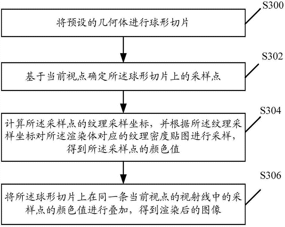
[0048] image 3 It shows a schematic flowchart of a volume rendering-based image rendering method provided by an embodiment of the present invention, including:

[0049] Step S300: performing spherical slicing on the preset geometry;

[0050] S...


PUM


Abstract

An embodiment of the invention discloses an image rendering method based on volume rendering. The image rendering method comprises the steps of: subjecting a preset geometry to spherical slicing; determining sampling points on spherical slices based on a current viewpoint, calculating texture sampling coordinates of the sampling points, and sampling a texture density map corresponding to a rendering body according to the texture sampling coordinates, so as to obtain color values of the sampling points; and superposing the color values of the sampling points in the same viewing ray of the current viewpoint on the spherical slices, so as to obtain a rendered image. The invention further discloses an image rendering device based on volume rendering. By adopting the image rendering method and the image rendering device, the GPU consumption time is shortened, the effect and efficiency of rendering the target geometry are greatly improved, and the requirement for processing capacity of a video card is decreased; and special processing is carried out for sea of clouds traversing, upward view of the sea of clouds and an environment below the sea of clouds when rendering the sea of clouds, so that the sea of clouds and the scene environment are integrated, and the effect is realistic and authentic.

Description

technical field [0001] The invention relates to the field of computer image rendering, in particular to an image rendering method based on volume rendering and an image rendering device based on volume rendering. Background technique [0002] Currently, volume rendering is the first method used in large-scale 3D games to represent large-scale volumetric clouds. In 3D games, the standard practice of volumetric clouds is to use particles to pile them up. However, when the scale reaches the level of the sea of ​​clouds, it is difficult to solve the problem of rendering efficiency, especially for online games compatible with low-end graphics cards, which have higher requirements for rendering efficiency. The rendering efficiency of classic volume rendering algorithms cannot meet the requirements of real-time rendering. Therefore, volumetric clouds for volume rendering can only be used in graphics software to bake static maps. [0003] In the prior art, volumetric clouds in 3D g...

Claims


Application Information

Patent Timeline
Patent Type & Authority Applications(China)
IPC IPC(8): G06T15/08
CPCG06T15/08
Inventor 马晓霏
Owner TENCENT TECH SHANGHAI
Why Eureka
Try Eureka