Wireless charging method and terminal

A technology of wireless charging and wireless charger, which is applied in the field of communication, can solve problems such as limitation, input voltage limitation, limitation, etc., and achieve the effect of improving charging efficiency and reducing charging time

Active Publication Date: 2019-12-27
BEIJING XIAOMI MOBILE SOFTWARE CO LTD
View PDF6 Cites 0 Cited by
  • Summary
  • Abstract
  • Description
  • Claims
  • Application Information

AI Technical Summary

Problems solved by technology

[0003] However, in the above two schemes, for the first scheme, due to the existence of the DC impedance and AC impedance of the receiving coil of the terminal, the coil will cause serious heating when the current exceeds a certain threshold, so the effect of increasing the power by continuously increasing the current It is relatively limited, and for the second solution, since the power management chip responsible for charging in the terminal has a limit on the input voltage, increasing the power by increasing the voltage will also be limited
It can be seen that due to the limitation of the terminal receiving coil and power management chip, the existing wireless charging scheme cannot effectively improve the power

Method used


Image

  • Wireless charging method and terminal
  • Wireless charging method and terminal
  • Wireless charging method and terminal

Examples


Embodiment Construction

[0019] Reference will now be made in detail to the exemplary embodiments, examples of which are illustrated in the accompanying drawings. When the following description refers to the accompanying drawings, the same numerals in different drawings refer to the same or similar elements unless otherwise indicated. The implementations described in the following exemplary examples do not represent all implementations consistent with the present disclosure. Rather, they are merely examples of terminals and methods consistent with aspects of the present disclosure as recited in the appended claims.

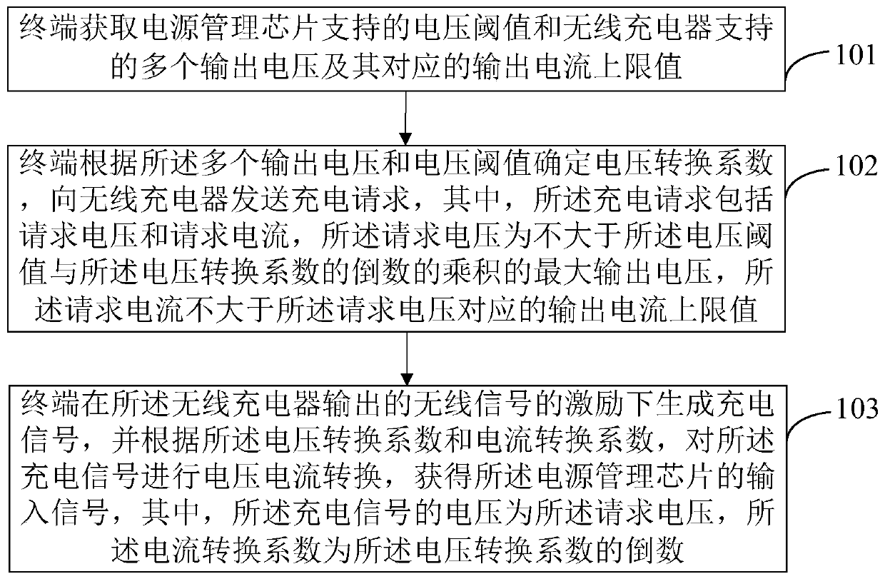
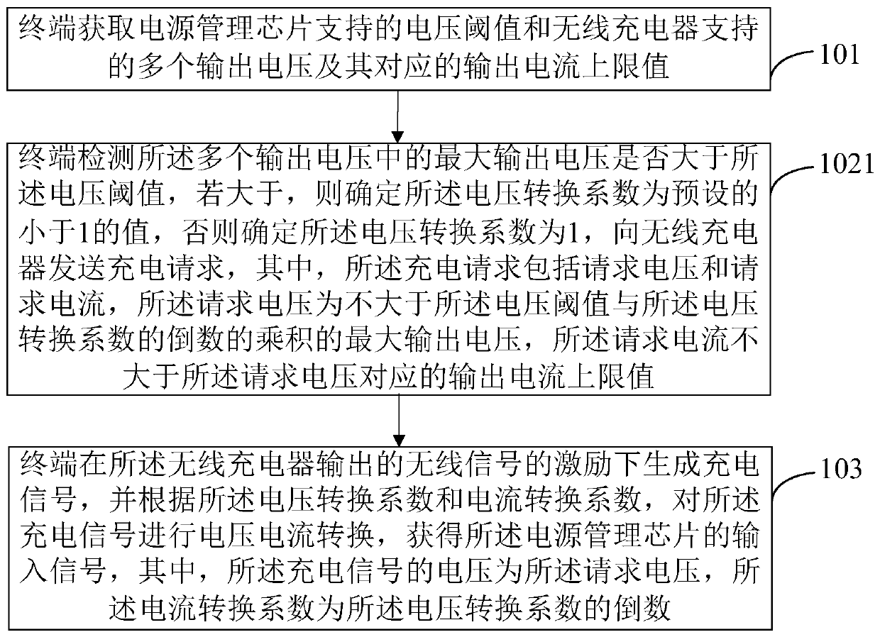
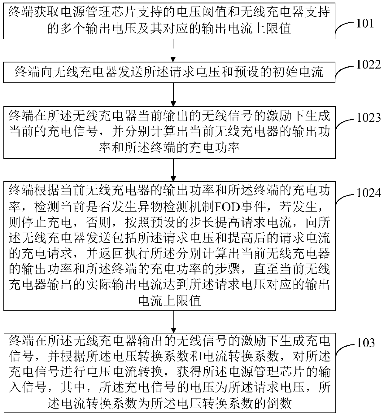
[0020] Figure 1A It is a flow chart of a wireless charging method shown according to an exemplary embodiment, as shown in Figure 1A As shown, this embodiment is illustrated by taking the wireless charging method applied to a terminal as an example. The wireless charging method may include the following steps:

[0021] In step 101, the terminal obtains the voltage threshold supported ...


PUM


Abstract

The present disclosure relates to a wireless charging method and a terminal. The method includes: the terminal obtains a voltage threshold supported by a power management chip, multiple output voltages supported by a wireless charger and their corresponding upper limit values ​​of output current; and the voltage threshold to determine the voltage conversion coefficient, and send a charging request to the wireless charger, wherein the charging request includes a requested voltage and a requested current, and the requested voltage is the maximum output voltage not greater than the product of the voltage threshold and the reciprocal of the voltage conversion coefficient, and the requested current is not It is greater than the upper limit of the output current corresponding to the requested voltage; the terminal generates a charging signal under the excitation of the wireless signal output by the wireless charger, and performs voltage and current conversion on the charging signal according to the voltage conversion coefficient and current conversion coefficient to obtain the input of the power management chip signal, where the current conversion factor is the reciprocal of the voltage conversion factor. The solution provided by the present disclosure can effectively improve charging efficiency and reduce charging time.

Description

technical field [0001] The present disclosure relates to the communication field, and in particular, to a wireless charging method and terminal. Background technique [0002] With the development of wireless charging technology, more and more terminals, including many wearable devices and smart terminals, begin to apply wireless charging technology. Specifically, the terminal to be charged acts as the receiving end of wireless charging, and converts the wireless signal sent by the transmitting end of wireless charging to obtain a corresponding charging signal. The charging signal is used to provide the input signal of the power management chip to enable the power management The chip charges the battery of the terminal. In wireless charging technology, in order to improve the power and efficiency of charging, two solutions need to be adopted: one is to increase the current of the wireless charging signal while keeping the voltage constant, thereby increasing the power; the o...

Claims


Application Information

Patent Timeline
Patent Type & Authority Patents(China)
IPC IPC(8): H02J7/00
CPCH02J7/0077H02J7/025H02J7/00034H02J50/10H02J50/80H02J50/60G05F1/577H02J7/00712G06F1/26H02J7/00714
Inventor 王彦腾
Owner BEIJING XIAOMI MOBILE SOFTWARE CO LTD
Why Eureka
Try Eureka