Hall switch offset voltage elimination method

A technology of offset voltage and Hall switch, applied in electronic switches, electrical components, pulse technology, etc., can solve the problem that the offset voltage of Hall switch cannot be completely eliminated

Inactive Publication Date: 2017-12-15
WUXI LINLI SCI & TECH CO LTD
View PDF4 Cites 3 Cited by
  • Summary
  • Abstract
  • Description
  • Claims
  • Application Information

AI Technical Summary

Problems solved by technology

[0007] The invention proposes a method for eliminating the offset voltage of the Hall switch, which solve

Method used


Image

  • Hall switch offset voltage elimination method
  • Hall switch offset voltage elimination method
  • Hall switch offset voltage elimination method

Examples


Embodiment Construction

[0024] The following will clearly and completely describe the technical solutions in the embodiments of the present invention with reference to the accompanying drawings in the embodiments of the present invention. Obviously, the described embodiments are only some, not all, embodiments of the present invention. Based on the embodiments of the present invention, all other embodiments obtained by persons of ordinary skill in the art without creative efforts fall within the protection scope of the present invention.

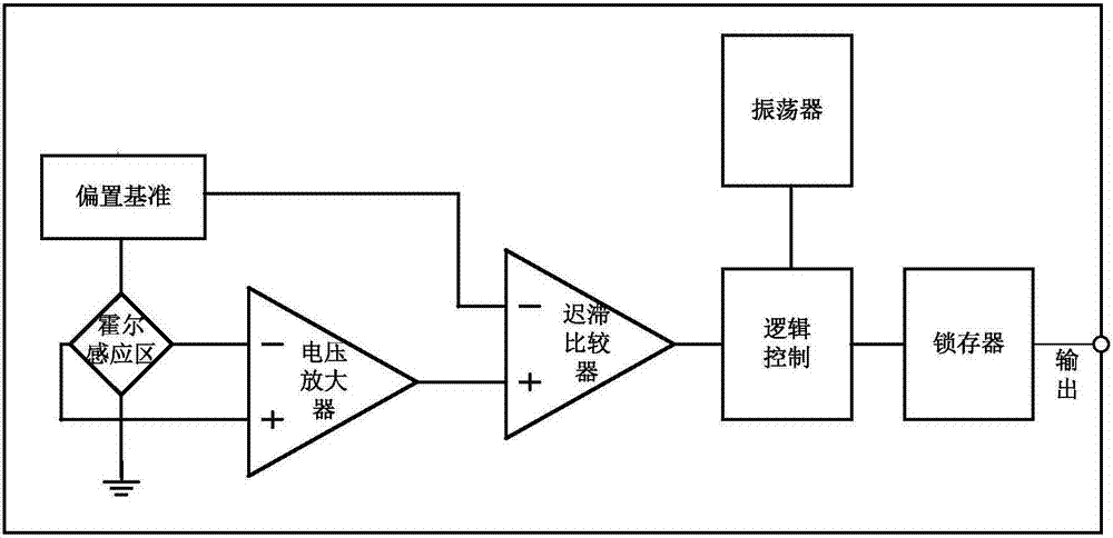
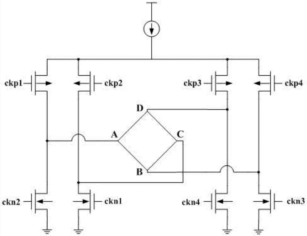
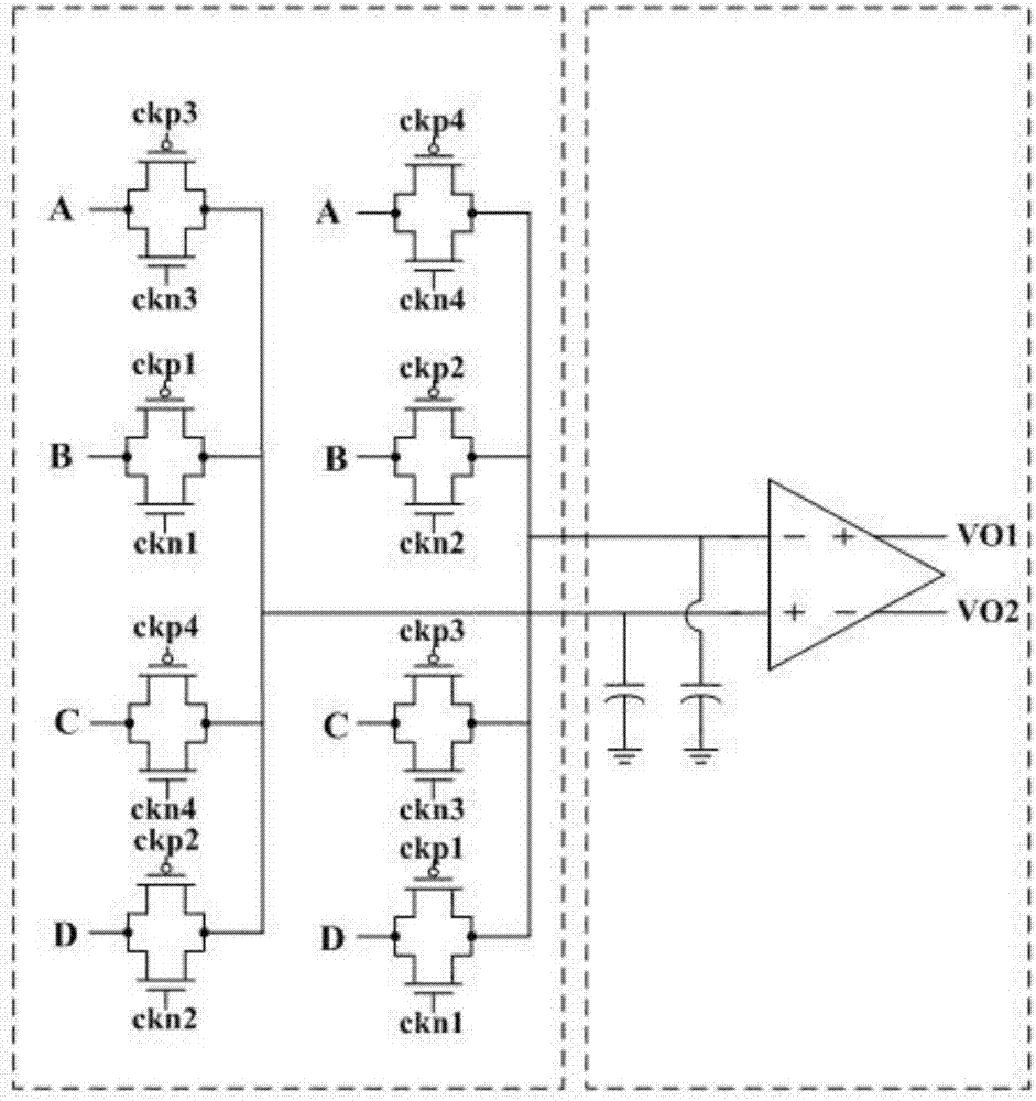
[0025] The Hall switch offset voltage elimination method includes a Hall sensing area, the Hall sensing area is connected to a constant current, and the Hall sensing area is respectively connected to four groups of non-overlapping switch signals in four directions, And the magnetic field signal is converted into the voltage signal of the induced electromotive force. The voltage signal uses four sets of switching clock signals to control the transmission gate and the...


PUM


Abstract

The invention provides a Hall switch offset voltage elimination method. The method comprises a Hall sensing area, wherein a constant current is accessed in the Hall sensing area, four groups of switch signals that are not overlapped with each other are accessed in the Hall sensing area in four directions, the Hall sensing area converts a magnetic field signal into a voltage signal of an induced electromotive force, the voltage signal uses four groups of switch clock signal to control a transmission gate and a differentiate amplifier to obtain a first amplification signal and a second amplification signal, and the four groups of switch signal average the first amplification signal and the second amplification signal so as to eliminate difference of the Hall voltages in four directions. Offset voltages in four directions of 360 degree are eliminated fully, a chopper amplifier is adopted for amplification so as to eliminate offset voltage caused by the circuit, so that offset voltage is eliminated finally, and a stable magnetic field flip point is obtained.

Description

technical field [0001] The invention belongs to the technical field of electromagnetic effects, in particular to a method for eliminating the offset voltage of a Hall switch. Background technique [0002] At present, the Hall effect is a kind of electromagnetic effect. This phenomenon was discovered by the American physicist Hall (A.H. Hall, 1855-1938) in 1879 when he was studying the conductive mechanism of metals. When the current passes through the conductor perpendicular to the external magnetic field, an additional electric field is generated perpendicular to the direction of the current and the magnetic field, thereby generating a potential difference at both ends of the conductor. This phenomenon is the Hall effect, and this potential difference is also called the Hall potential difference. [0003] The Hall switch designed using the Hall effect has the characteristics of no contact, low power consumption, long service life, high response frequency, and good reliabili...

Claims


Application Information

Patent Timeline
IPC IPC(8): H03K17/90
CPCH03K17/90
Inventor 姜建华
Owner WUXI LINLI SCI & TECH CO LTD
Why Eureka
Try Eureka