Eight-phase current rotating circuit for Hall sensor

A Hall sensor and current circuit technology, applied in logic circuits, logic circuit interface devices, eliminating voltage/current interference, etc., can solve the problems of large residual offset, low residual offset, large noise and interference of offset elimination circuit, etc., to achieve Strong anti-interference ability, simple technical solution, low residual offset effect

Active Publication Date: 2017-11-03
NANJING UNIV OF POSTS & TELECOMM
View PDF6 Cites 1 Cited by
  • Summary
  • Abstract
  • Description
  • Claims
  • Application Information

AI Technical Summary

Problems solved by technology

The widely used dynamic offset cancellation circuit is based on the traditional two-phase rotating current technology. However, the effect of the two-phase rotating current technology on eliminating the Hall offset is not ideal, and the residual offset is large, resulting in the magnetic field resolution of the Hall sensor is not high enough, and it is difficult to meet high Accurate, high-resolution magnetic field detection requirements, so four-phase and eight-phase rotating current technology must be used
[0003] Compared with the four-phase rotating current technology, the eight-phase rotating current technology performs rotating current operation in 8 symmetrical directions of the Hall device, which has a better effect of eliminating the offset of the Hall device and can obtain lower residual offset. However, the eight-phase The timing and circuit structure of the spinning current circuit is more complicated
On the other hand, the modulation and demodulation technology of the eight-phase rotating current is still immature, and the characteristics of the polarity change of the Hall signal and the offset signal during the eight-phase rotating current cannot be fully utilized to eliminate the distortion of the Hall device and the amplifier circuit to the greatest extent. out of balance
In addition, Hall devices generally adopt the working mode of Hall voltage output. However, the offset elimination circuit of this voltage mode is easily affected by the effect of parasitic capacitance and introduces a lot of noise and interference, thereby reducing the signal-to-noise of the Hall sensor. Compare

Method used


Image

  • Eight-phase current rotating circuit for Hall sensor
  • Eight-phase current rotating circuit for Hall sensor
  • Eight-phase current rotating circuit for Hall sensor

Examples


Embodiment Construction

[0026]Now the patent of the present invention is described in further detail in conjunction with the accompanying drawings.

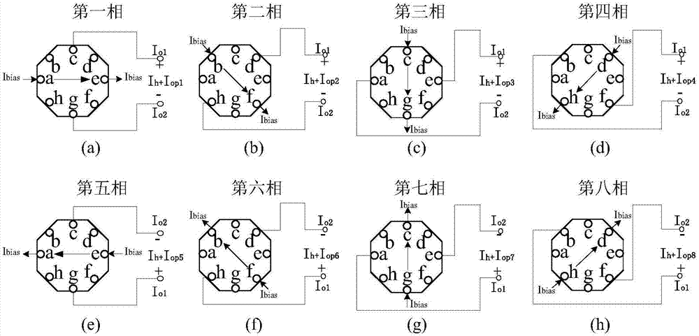
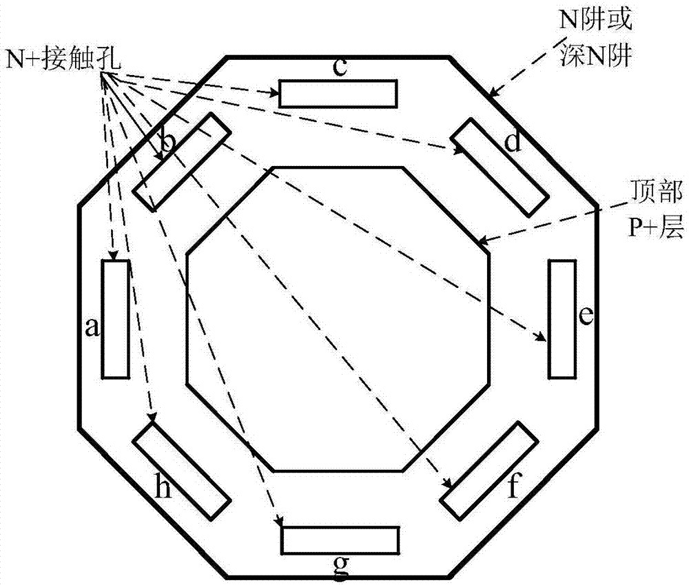
[0027] An eight-phase rotating current circuit based on the current output mode proposed by the present invention, its working principle is as follows figure 1 shown. The eight-hole Hall device works in the current output mode, that is, the bias current I bias It flows in from one input port of the Hall device, and then flows out from another output port parallel to the input port. The other two output ports perpendicular to the input port of the eight-hole Hall device output a differential current signal, and the differential current signal is an aliasing signal of the Hall current and the offset current. The schematic diagram of the structure of the eight-hole Hall device is as follows: figure 2 shown. The eight-hole Hall device has a 45° rotational symmetry structure, with a regular octagonal N well or a deep N well as the active area of ​​the H...


PUM


Abstract

The invention provides an eight-phase current rotating circuit for a Hall sensor, and discloses an eight-phase current rotating circuit based on the current output mode and a dynamic offset cancellation method for the eight-phase current rotating circuit. The eight-phase current rotating circuit is composed of 32 NMOS transistors, wherein 16 NMOS transistors with the same size control the input and output directions of a bias current, and the other 16 NMOS transistors with the same size control the output polarity of a Hall signal and an offset signal. The eight-port Hall device with a 45-degree rotational symmetry structure is controlled by an eight-phase sequence clock to conduct eight-phase current rotating operation to output the Hall signal of which the polarity does not change and the offset signal of which the polarity changes. The dynamical offset cancellation technical scheme is simple, the circuit is easy to achieve, and by outputting the offset signal of which the polarity changes and the Hall signal of which the polarity does not change in the eight-phase current rotating modulation process and by means of follow-up current integration amplification and sampling/keeping and subtracting operation, offset of the Hall device can be effectively cancelled, and very low residual offset can be achieved.

Description

technical field [0001] The invention belongs to the technical field of magnetic sensors, and in particular relates to an eight-phase rotating current circuit for a Hall sensor and a dynamic offset elimination method, which can enable the Hall sensor to obtain very low residual offset. Background technique [0002] The Hall magnetic field sensor is a magnetoelectric conversion element based on the Hall effect. The CMOS integrated Hall sensor has many advantages such as small size, low cost, low power consumption, fast response, and strong anti-interference ability. It has been widely used in many fields such as automotive electronics, communication, medical treatment and instrument manufacturing. However, the CMOS integrated Hall sensor has serious problems of low magnetic field sensitivity and high offset. Layout alignment errors during Hall device lithography, uneven carrier distribution caused by ion implantation in the active area of ​​the device, piezoresistive effect c...

Claims


Application Information

Patent Timeline
Patent Type & Authority Applications(China)
IPC IPC(8): H03K19/00H03K19/003H03K19/0175
CPCH03K19/0008H03K19/00346H03K19/017509
Inventor 徐跃李鼎赵庭晨
Owner NANJING UNIV OF POSTS & TELECOMM
Why Eureka
Try Eureka