Ultrasonic scanner and detection method thereof

A scanner and ultrasonic technology, applied in instruments, using sound waves/ultrasonic waves/infrasonic waves to analyze solids, using sound waves/ultrasonic waves/infrasonic waves for material analysis, etc., can solve the problems of inconvenient disassembly and maintenance, complex design structures, and inability to guarantee high precision Ground scanning inspection and other problems, to achieve the effect of easy installation and adjustment, simple structure, and shortened detection time

Active Publication Date: 2017-12-19
CHINA AERO POLYTECH ESTAB
View PDF13 Cites 8 Cited by
  • Summary
  • Abstract
  • Description
  • Claims
  • Application Information

AI Technical Summary

Problems solved by technology

At present, the scanner can mainly scan three representative structures: flat plate butt joint, pipe butt joint with different curvature, and fillet weld structure with different angles. Existing scanners can only scan for one or two structures at present. In addition, the design and structure of existing scanners are generally complicated, which is not easy to disassemble and maintain, and cannot guarantee high-precision scanning and detection, which limits their use under complex working conditions

Method used


Image

  • Ultrasonic scanner and detection method thereof
  • Ultrasonic scanner and detection method thereof
  • Ultrasonic scanner and detection method thereof

Examples


Embodiment Construction

[0032] Exemplary embodiments, features, and aspects of the present invention will be described in detail below with reference to the accompanying drawings. The same reference numbers in the figures indicate functionally identical or similar elements. While various aspects of the embodiments are shown in drawings, the drawings are not necessarily drawn to scale unless specifically indicated.

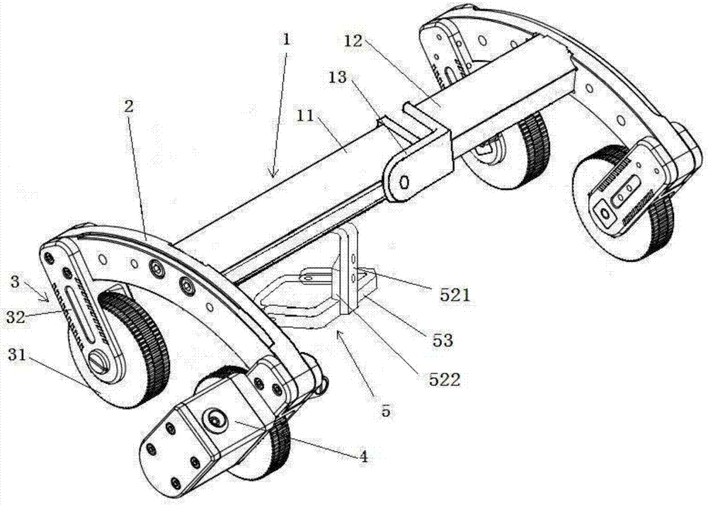
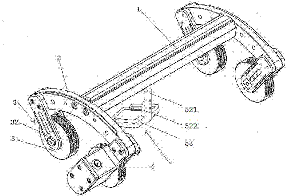
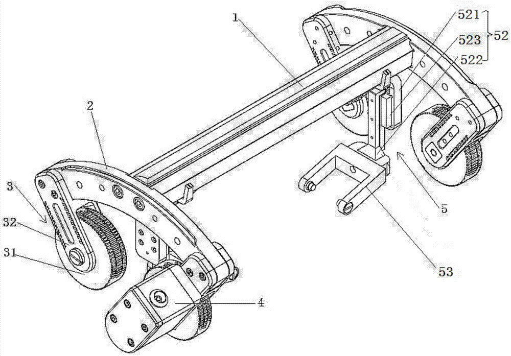
[0033] Such as figure 1 As shown, an ultrasonic scanner includes a main beam 1, an arc arm 2, a magnetic wheel mechanism 3, an encoder 4, and a probe loading arm 5. The main beam 1 includes a long arm 11, a short arm 12 and a connecting long arm 11 and the connecting piece 13 of the short arm 12, the connecting piece 13 is configured to adjust the angle between the long arm 11 and the short arm 12, the angle between the long arm 11 and the short arm 12 is 0-180 °, the long arm 11 and the upper surface of the short arm 12 are provided with scale marks (not shown), the first side of the l...


PUM


Abstract

The invention belongs to the technical field of ultrasonic non-destructive detection, and relates to an ultrasonic scanner, which comprises a main beam, arc-shaped arms, magnet-wheel mechanisms, encoders and a probe loading arm. The main beam comprises a long arm, a short arm, and a connecting piece used for connecting the long arm and the short arm and capable of adjusting an included angle between the long arm and the short arm; the arc-shaped arms are connected to two end parts of the main beam; the magnet-wheel mechanisms are respectively connected to two ends of the arc-shaped arms through connecting arms; the encoders used for recording distances are arranged on the arc-shaped arms; each magnet-wheel mechanism comprises a magnetic wheel and a demagnetizing device; each connecting arm can adjust the distance and the angle between the magnetic wheels located at two ends of each arc-shaped arm; each demagnetizing device is fixed onto the corresponding connecting arm; the probe loading arm comprises a second slide block, a loading arm and a probe fixing rack; the probe loading arm can slide in a length direction of the main beam; the probe loading arm can be disassembled and replaced. The ultrasonic scanner provided by the invention can be used for simultaneously scanning three weld joints, i.e. a straight welded joint, a circumferential weld joint and a fillet weld joint, and is good in flexibility, and high in accuracy and reliability.

Description

technical field [0001] The invention belongs to the technical field of ultrasonic nondestructive testing, and relates to an ultrasonic scanner and a testing method thereof. Background technique [0002] Ultrasonic non-destructive testing methods play an irreplaceable role in product quality testing and equipment safety performance testing in many industrial fields. With the development of non-destructive testing technology, ultrasonic testing is gradually developing in the direction of imaging and recording. For important and complex structural parts, imageable advanced ultrasonic testing methods such as phased array ultrasonic (PAUT) and time-of-flight diffraction (TOFD) are increasingly becoming mainstream testing methods. The high-precision, portable, and multi-purpose mechanical scanner is a key component to realize the engineering application of this technology. The scanner is mainly used to clamp the probe and move on the detection surface to realize high-precision ul...

Claims


Application Information

Patent Timeline
IPC IPC(8): G01N29/04G01N29/22G01N29/24
CPCG01N29/04G01N29/223G01N29/24G01N2291/0234G01N2291/2675
Inventor 刘志毅王俊涛张祥春郑友博周言贤刘安
Owner CHINA AERO POLYTECH ESTAB
Why Eureka
Try Eureka