
Electronic parking mechanism of automatic transmission

An automatic transmission, electronic parking technology, applied in the direction of brakes, braking components, vehicle components, etc., can solve the problems of mechanical loss, affecting the comfort of the driver, affecting the parking force of the shift handle, etc., to improve the rigidity and use. Long life, less wear and longer life effect

Pending Publication Date: 2017-12-22
CHONGQING TSINGSHAN IND +1
View PDF6 Cites 7 Cited by
  • Summary
  • Abstract
  • Description
  • Claims
  • Application Information

AI Technical Summary

Problems solved by technology

Most of the parking mechanisms used in the market today are manual parking mechanisms. The manual parking mechanism usually transmits the movement of the handbrake to the parking pawl by the complex transmission mechanism in the manual parking mechanism. loss, the driver needs to use more force to pull the handbrake to complete the parking action
On the other hand, it will affect the parking force of the shift handle due to the different road conditions such as uphill, downhill, and flat roads of the vehicle, thereby affecting the comfort of the driver in or out of the parking gear; in addition, if the shift force To make it moderate in size, it is necessary to add some parts or structures to adjust the shifting force
Since the layout of various components and structures in the manual parking mechanism will affect the overall structural layout of the handle, transmission and vehicle, the design and layout of the parking mechanism is not flexible enough

Method used


Image

  • Electronic parking mechanism of automatic transmission
  • Electronic parking mechanism of automatic transmission
  • Electronic parking mechanism of automatic transmission

Examples


Embodiment Construction

[0031] Referring to the accompanying drawings, specific embodiments of the present invention will be described in detail.

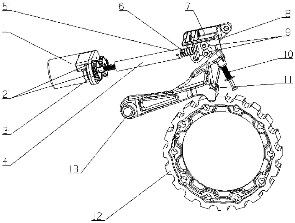
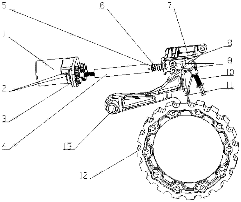
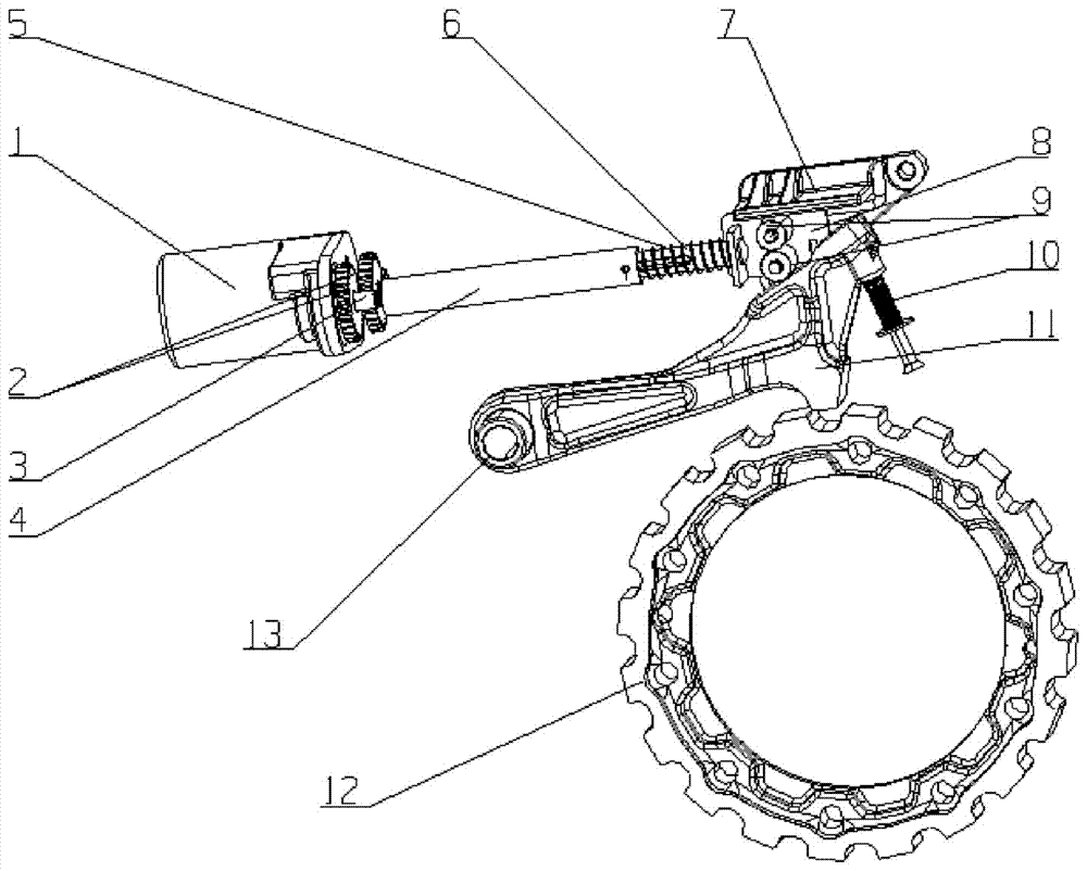
[0032] see Figure 1 to Figure 7 , an embodiment of the automatic transmission electronic parking mechanism, the automatic transmission electronic parking mechanism includes a parking motor 1, a parking ratchet 12 and a parking pawl 11, and the parking motor 1 is installed and fixed on the transmission case , the rotating shaft of the parking motor 1 is connected with a screw rod 3 through a reduction gear mechanism 2 . The reduction gear mechanism 2 includes a support plate 23, an input gear 19, a reduction dual gear, and an output gear 22. The support plate 23 is provided with an intermediate shaft 24, and the reduction dual gear is slidably fitted on the intermediate shaft 24. The screw rod 3 is rotatably supported on the support plate 23, the output gear 22 is fixedly connected with the screw rod 3 and meshed with the pinion 21 of the deceleration do...


PUM


Abstract

The invention relates to an electronic parking mechanism of an automatic transmission. The electronic parking mechanism comprises a parking motor, a parking ratchet wheel and a parking pawl, wherein the parking motor is installed and fixed to a transmission box body, a rotary shaft of the parking motor is connected with a screw through a speed-reducing gear mechanism, the screw is matched with one end of an internal threaded sleeve in a threaded mode, a linear telescopic push rod is arranged inside the other end of the internal threaded sleeve through sliding fit and extends out, a roller is arranged at the outward extending end of the linear telescopic push rod, the outward extending section of the linear telescopic push rod is sleeved with a compression spring, the upper end face of the roller on the linear telescopic push rod is in contact with a lower-end guiding face of a guiding plate fixed to the transmission box body, the tail end of the parking pawl is a fixed end, the fixed end is hinged to the transmission box body, the head end of the parking pawl is a free end, downward extending pawl teeth are arranged at the lower portion of the free end, a sloping surface is arranged at the upper portion of the free end, toothed grooves are uniformly distributed in the circumference of the parking ratchet wheel, and an unlocking reset device is arranged on the transmission box body and corresponds to the free end of the parking pawl.

Description

technical field [0001] The invention relates to a parking mechanism, in particular to an electronic parking mechanism of an automatic transmission. Background technique [0002] With the development of the automobile market, the proportion of automatic transmissions in the transmission market continues to increase. The safety of automatic transmission is an important factor that needs to be considered in automatic transmission vehicles. The function of the parking mechanism is to lock the transmission system when the vehicle is stationary to ensure parking safety. It is an important device necessary for automatic transmission vehicles. Its performance is directly related to the safety of the owner's life and property. Most of the parking mechanisms used in the market today are manual parking mechanisms. The manual parking mechanism usually transmits the movement of the handbrake to the parking pawl by the complex transmission mechanism in the manual parking mechanism. If t...

Claims


Application Information

Patent Timeline
IPC IPC(8): B60T1/06B60T11/04
CPCB60T11/04B60T1/062
Inventor 张建华邸永峰杜一廖兴阳严世勇胡家路杨鸿淳登松赵拼
Owner CHONGQING TSINGSHAN IND
Learn More