Auto part unloading mechanism

A technology for auto parts and clamping mechanism, which is applied to conveyor objects, transportation and packaging, etc., and can solve problems such as product surface damage, product scrapping, paint peeling, etc.

Active Publication Date: 2017-12-22
浙江康意智能科技有限公司
View PDF7 Cites 11 Cited by
  • Summary
  • Abstract
  • Description
  • Claims
  • Application Information

AI Technical Summary

Problems solved by technology

Although there is only a very thin layer (0.05-0.15mm), it has a great impact on the performance of machine parts; the wear, corrosion and fatigue damage of parts all start from the surface of parts, especially modern industrial production makes machines It is developing in the direction of precision, high speed, and multi-function. For mechanical parts working under high temperature, high pressure, high speed, and high stress conditions, any defects on the surface layer will accelerate the failure of the parts.
Therefore, we must pay attention to the surface quality of machining. The research found that most of the surface quality comes from human factors, such as taking materials without gloves, sweat stains on hands will affect the anti-corrosion of metals, and fingerprints will affect the spraying effect of parts after processing. , In severe cases, there will be poor coating and paint falling off. In addition, violent operations during loading and unloading will also cause collisions with auto parts, which will easily cause damage to auto parts, and eventually lead to the scrapping of the entire product, resulting in a certain degree of economic loss.
[0004] The processing of auto parts has now realized the processing of continuous production lines. After a variety of processes, the feeding system of automatic manipulators has been perfected, but most of the unloading is still manual unloading, which is time-consuming and laborious, and it is easy to cause surface damage to the product. damage

Method used


Image

  • Auto part unloading mechanism
  • Auto part unloading mechanism
  • Auto part unloading mechanism

Examples


Embodiment Construction

[0026] The following will clearly and completely describe the technical solutions in the embodiments of the present invention with reference to the accompanying drawings in the embodiments of the present invention. Obviously, the described embodiments are only some, not all, embodiments of the present invention. Based on the embodiments of the present invention, all other embodiments obtained by persons of ordinary skill in the art without making creative efforts belong to the protection scope of the present invention.

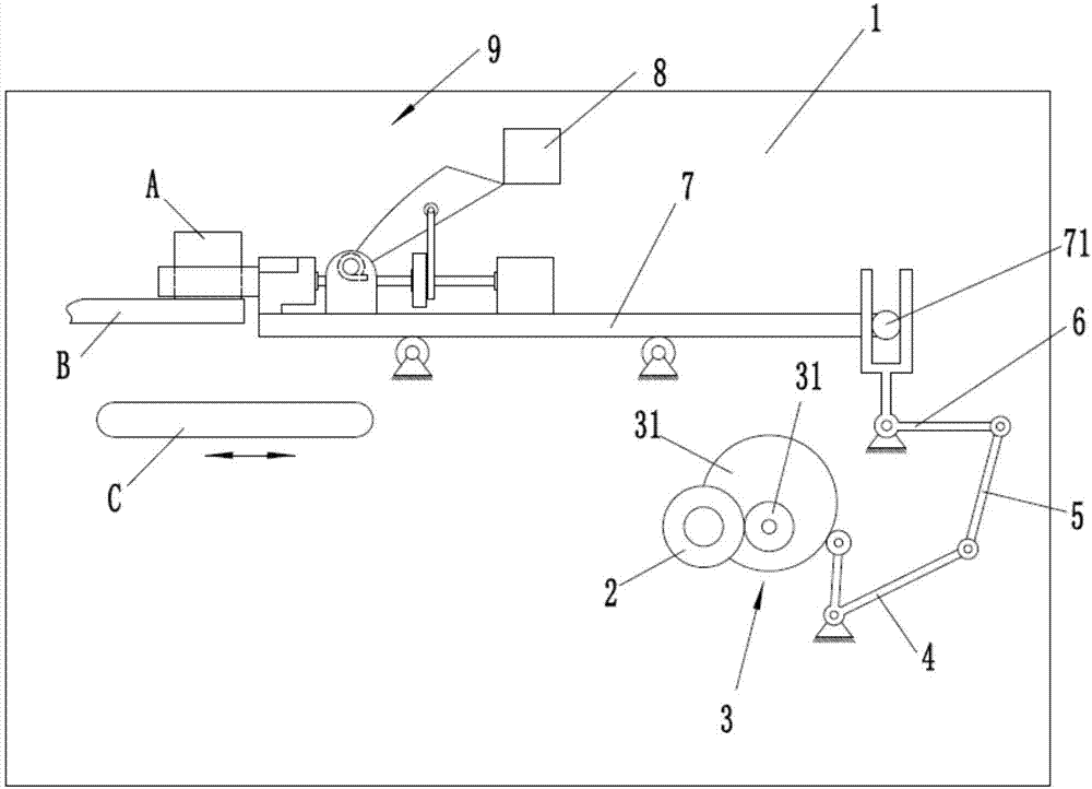
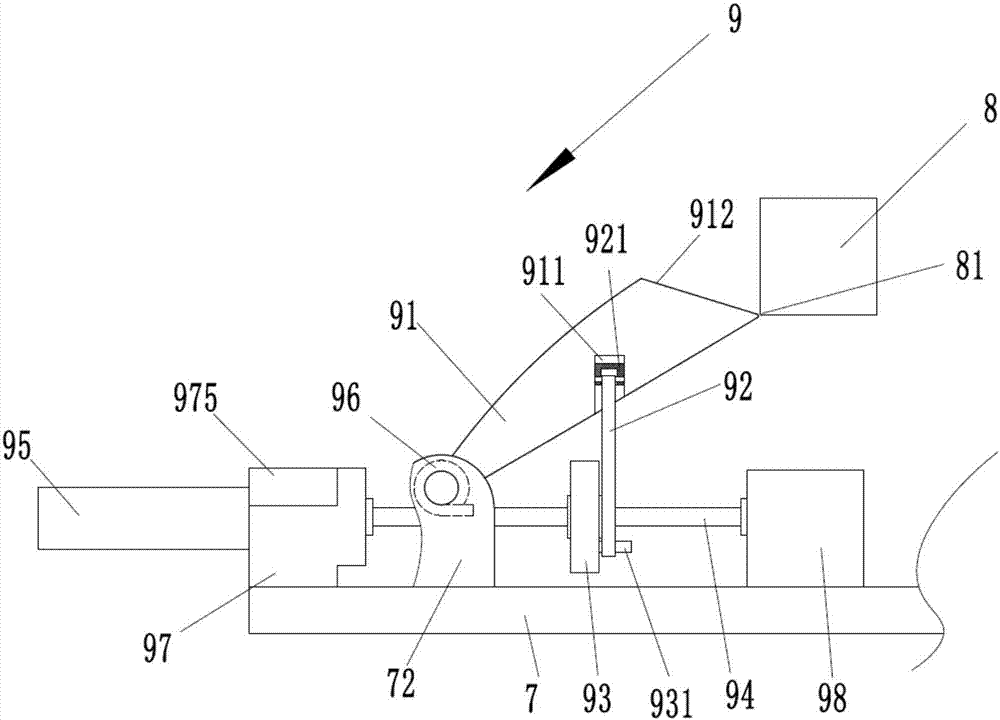
[0027] refer to Figure 1 to Figure 5 ,Such as figure 1 The blanking mechanism for auto parts shown includes a vertically arranged fixed frame 1, a stopper 8 is fixed above the fixed frame 1, and a driving wheel 2 is fixed below the fixed frame 1, and the driving wheel 2 drives the driven wheel 3 to rotate , the driven wheel 3 is composed of a gear 31 and a cam 32, the driving wheel 2 drives the gear 31 to rotate, the gear 31 drives the cam 32 to rotate toget...


PUM


Abstract

The invention discloses an auto part unloading mechanism. The auto part unloading mechanism comprises a vertically arranged fixed rack. A baffle plate is fixed at the upper portion of the fixed rack; a driving wheel is fixed at the lower portion of the fixed rack; the driving wheel drives a driven wheel to rotate; the driven wheel is composed of a gear I and a cam; the driving wheel drives the gear I to rotate; the gear I drives the cam to rotate; the cam drives a swing arm to swing; a rocker is also hinged to the fixed rack; the swing arm drives the rocker to swing through a connecting rod; a supporting plate is also horizontally arranged on the fixed rack; a rotary shaft is arranged on the right end of the supporting plate; the rocker drives the rotary shaft to drive the supporting plate to reciprocate; the auto part unloading mechanism also comprises a clamping mechanism arranged on the supporting plate. By means of the reciprocating motion of the supporting plate, the clamping mechanism can clamp and unload auto parts automatically. As a special clamping mechanism is adopted, the auto part unloading mechanism can clamp and unload auto parts automatically.

Description

technical field [0001] The invention relates to the technical field of auto parts, in particular to a feeding mechanism for auto parts. Background technique [0002] Auto parts are a product that constitutes the overall structure of the car. With the improvement of people's living standards, people's consumption demand for cars is also increasing, and the market for auto parts is becoming larger and larger. Nowadays, China has become a global The third largest automobile producer and the second largest automobile consumer market, the auto parts industry has entered a period of rapid development. [0003] With the increasingly fierce competition in the auto parts processing market, the concept of quality has been deeply rooted in the hearts of the people, and people have become more and more picky about the surface quality of parts. The surface quality of parts is an important part of machining quality. Surface quality refers to the quality of machining Changes in the micro-...

Claims


Application Information

Patent Timeline
Patent Type & Authority Applications(China)
IPC IPC(8): B65G47/90
Inventor 翁景坚杨向前
Owner 浙江康意智能科技有限公司
Why Eureka
Try Eureka