Laser light source and projection display device

A laser light source, laser array technology, applied in optics, instruments, projection devices, etc., can solve problems such as complex optical path structure

Inactive Publication Date: 2017-12-22
HISENSE VISUAL TECH CO LTD
View PDF4 Cites 33 Cited by
  • Summary
  • Abstract
  • Description
  • Claims
  • Application Information

AI Technical Summary

Problems solved by technology

[0004] However, in the laser light source in the prior art, after the laser light is transmitted through the fluorescent wheel 5, it needs to be diverted through the relay circuit before

Method used


Image

  • Laser light source and projection display device
  • Laser light source and projection display device
  • Laser light source and projection display device

Examples


Embodiment 1

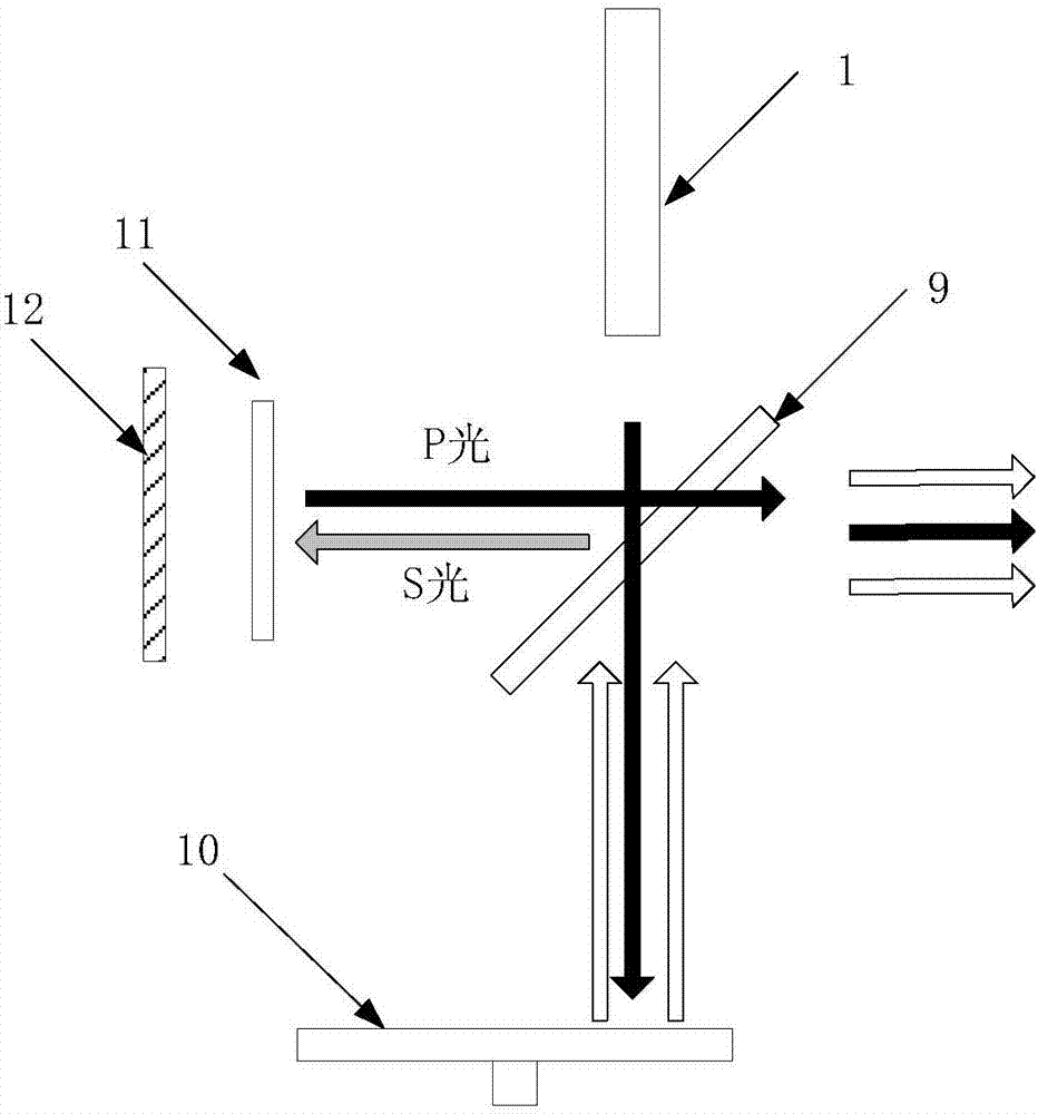
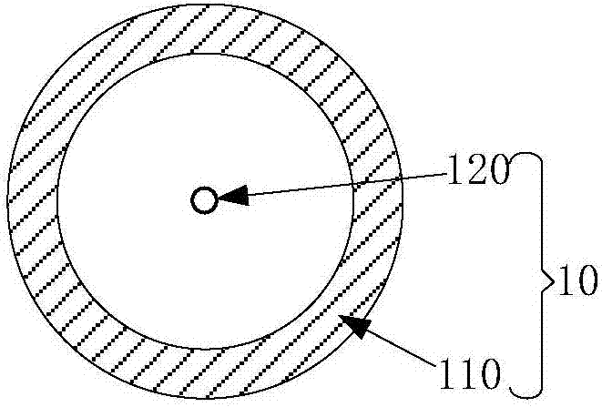
[0024] An embodiment of the present invention provides a laser light source, such as figure 2 As shown, it includes a laser array 1 that emits at least the first blue polarized light and the third blue polarized light, a reflective fluorescent wheel 10, a 1 / 4 wave plate 11, a mirror 12 and is arranged on the laser array 1 and the Polarizing dichroic assembly 9 between reflective fluorescent wheels 10 described above. in,

[0025] The polarization dichroic component 9 is obliquely arranged between the laser array 1 and the reflective fluorescent wheel 10 .

[0026] The 1 / 4 wave plate 11 is arranged on one side of the polarization dichroic component 9 for receiving the first blue polarized light reflected by the polarization dichroic component 9, and the 1 / 4 wave plate 11 and the polarization dichroic component 9 The optical path transmission direction between them is perpendicular to the optical path transmission direction between the laser array 1 and the reflective fluores...

Embodiment 2

[0058] The difference between the laser light source provided by the embodiment of the present invention and the first embodiment is that the laser array 1 can also emit the first red polarized light, such as Figure 6 As shown, the laser array 1 not only includes a blue laser array 13 that emits first blue polarized light and a third blue polarized light, but also includes a red laser array 14 that can emit first red polarized light.

[0059] The first red polarized light emitted by the red laser array 14 is irradiated on the polarization dichroic component 9, and the polarization dichroic component 9 reflects the first red polarized light to the 1 / 4 wave plate 11; the 1 / 4 wave plate 11 receives the first red polarized light A red polarized light, and rotate the polarization direction of the first red polarized light by 45°, convert it into the second red polarized light and transmit it to the reflector 12; the reflector 12 reflects the obtained second red polarized light to 1...

Embodiment 3

[0066] Based on the above technical solution, the embodiment of the present invention also provides a projection display device, such as Figure 7 As shown, it includes a laser light source 1001 , an optical machine 1002 , a lens 1003 and a projection screen 1004 .

[0067] The laser light source 1001 adopts the laser light source in the above-mentioned embodiment, and outputs laser light and fluorescent light in a non-sequential manner, and the output laser light and fluorescent light enter the optical machine 1002. Taking the optical machine composed of LCOS chips as an example, the laser light and fluorescent light output by the laser light source follow the After the beams of different colors are split, they are respectively modulated by the LCOS chip, converge to reach the lens 1003 , and finally image on the projection screen 1004 .


PUM


Abstract

The present invention discloses a laser light source and a projection display device. The laser light source comprises a laser array at least sending out the first blue polarized light and the third blue polarized light, a reflective fluorescent wheel, a 1/4 wave plate, a reflector and a polarized dichroic assembly arranged between the laser array and the reflective fluorescent wheel, wherein the reflective fluorescent wheel is equipped with a fluorescence reflection area, the 1/4 wave plate receives the first blue polarized light reflected by the polarized dichroic assembly, converts the first blue polarized light into the second blue polarized light, also receives the second blue polarized light reflected by the reflector and converts the second blue polarized light into the third blue polarized light, and the polarized dichroic assembly transmits the third blue polarized light coming from the 1/4 wave plate and the laser array and reflects the fluorescence generated when the third blue polarized light coming from the laser array irradiates the fluorescence reflection area. The laser light source is few in optical assemblies, and enables the laser loss to be reduced substantially and the laser utilization rate to be improved substantially.

Description

technical field [0001] The invention relates to the technical field of laser display, in particular to a laser light source and projection display equipment. Background technique [0002] With the continuous improvement of market demand, more and more high-brightness, large-size, high-resolution projectors have attracted more and more attention from the market. Laser light sources have begun to be used in projector technology due to their advantages such as high luminous power per unit area, long service life, and good color. However, due to the immaturity and low efficiency of the green laser array, phosphor powder is usually used in the laser light source, and the laser is used to excite the phosphor powder to emit green and other colors of fluorescence, thereby providing R, G, and B light for the projector. [0003] At present, laser light sources commonly used in projectors, such as figure 1 As shown, it includes a laser array 1; a diffuser 2 arranged in the light emit...

Claims


Application Information

Patent Timeline
IPC IPC(8): G03B21/20
CPCG03B21/204G03B21/2066G03B21/2073G03B21/208
Inventor 李巍
Owner HISENSE VISUAL TECH CO LTD
Why Eureka
Try Eureka