Offset calibration and rail-to-rail input combined comparator

A comparator and input terminal technology, applied in the direction of analog/digital conversion calibration/test, electrical components, code conversion, etc., can solve problems affecting ADC linearity, large offset voltage, offset voltage, etc., achieve simple structure and expand the scope of application Effect

Inactive Publication Date: 2017-12-22
UNIV OF ELECTRONICS SCI & TECH OF CHINA
View PDF4 Cites 9 Cited by
  • Summary
  • Abstract
  • Description
  • Claims
  • Application Information

AI Technical Summary

Problems solved by technology

A key issue that needs to be considered in comparator design is the offset voltage. The offset voltage is mainly caused by the mismatch of the threshold voltage of the input pair and the mismatch of the aspect ratio. However, the offset voltage of a general dynamic comparator is very large, which will seriously affect the ADC. linearity, so the offset voltage of the comparator needs to be calibrated
At the same time, with the expansion of the voltage range output by the image sensor readout circuit, since the input terminal of the single-slope ADC is the input terminal of the comparator, this requires the comparator to work normally within a large input voltage range. However, for general The comparator has a threshold voltage limit. When the input voltage is less than or greater than a certain value, the comparator input tube cannot be turned on normally, and the comparison result cannot be obtained.

Method used


Image

  • Offset calibration and rail-to-rail input combined comparator
  • Offset calibration and rail-to-rail input combined comparator
  • Offset calibration and rail-to-rail input combined comparator

Examples


Embodiment Construction

[0017] Below in conjunction with accompanying drawing and specific embodiment, the present invention is described in detail:

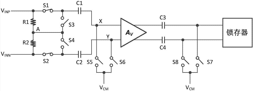
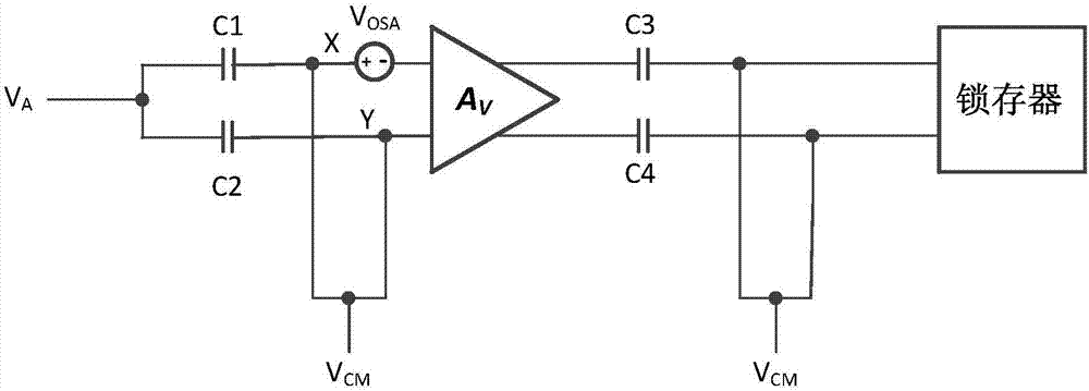
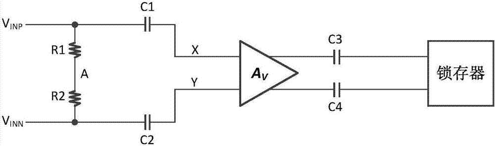
[0018] In this embodiment, the comparator proposed by the present invention is applied to a single-slope analog-to-digital converter, figure 1 It is the circuit structure diagram of the comparator proposed by the present invention. The resistance values ​​of the first resistor R1 and the second resistor R2 are equal, and the intermediate voltage value V of the two input signals input to the two input terminals of the comparator is obtained after series voltage division. A , as a reset signal for the plates on the first capacitor C1 and the second capacitor C2. The first capacitor C1 and the second capacitor C2 sample the input signal and convert it to a common-mode voltage V CM is a differential signal with a common-mode level, where the common-mode voltage V CM The value of is determined by the common-mode input level of the preamplifier, and its va...


PUM


Abstract

The invention relates to an offset calibration and rail-to-rail input combined comparator, and belongs to the technical field of analogue integrated circuits. A first resistor and a second resistor are connected between the two input ends of the comparator in series; the two input ends of the comparator are connected to the upper polar plates of a first capacitor and a second capacitor through a first switch and a second switch separately; the serial connection point of the first resistor and the second resistor is connected to the upper polar plates of the first capacitor and the second capacitor through a third switch and a fourth switch separately; the two input ends of a pre-amplifier are separately connected to the lower polar plates of the first capacitor and the second capacitor; the two output ends of the pre-amplifier are connected to the two input ends of a latch through a third capacitor and a fourth capacitor separately; the two input ends of the pre-amplifier are connected to common-mode voltage through a fifth switch and a sixth switch separately; and the two input ends of the latch are connected to common-mode voltage through a seventh switch and an eighth switch separately. The comparator provided by the invention has an offset calibration function; simultaneously, the input range is enlarged to rail-to-rail; and thus, the application range is enlarged.

Description

technical field [0001] The invention belongs to the technical field of analog integrated circuits, and relates to a comparator suitable for single-ended signal comparison, in particular to a rail-to-rail input comparator with offset calibration for a single-slope analog-to-digital converter (single-slope ADC) device. Background technique [0002] The function of an analog-to-digital converter (ADC) is to convert an analog signal into a digital signal, and it is a bridge connecting the analog world and the digital world. In recent years, due to the rapid growth of demand for portable electronic products, the rapid development of video technology, and the continuous improvement of CMOS process manufacturing technology, CMOS image sensors have made great progress. As an important part of the CMOS image sensor, the analog-to-digital converter plays a decisive role in the image quality and operating speed of the entire image sensor. [0003] The ADCs involved in image sensors s...

Claims


Application Information

Patent Timeline
Patent Type & Authority Applications(China)
IPC IPC(8): H03M1/10
CPCH03M1/1009
Inventor 唐鹤陈科全
Owner UNIV OF ELECTRONICS SCI & TECH OF CHINA
Why Eureka
Try Eureka