Patch type power inductor and manufacturing method thereof

A technology of power inductors and manufacturing methods, which is applied in the field of chip-type power inductors and their manufacturing, can solve problems such as poor heat dissipation performance, poor anti-saturation performance, and reduced reliability, so as to increase the heat dissipation area and improve anti-saturation Ability, life-prolonging effect

Pending Publication Date: 2017-12-26
SHENZHEN ZHENHUA FU ELECTRONICS +1
View PDF14 Cites 0 Cited by
  • Summary
  • Abstract
  • Description
  • Claims
  • Application Information

AI Technical Summary

Problems solved by technology

[0003] 1. The heat dissipation performance is not good, it is easy to age the coil and reduce the reliability;
[0004] 2. The anti-saturation performance is poor, and it is easy to burn the device due to high current

Method used


Image

  • Patch type power inductor and manufacturing method thereof
  • Patch type power inductor and manufacturing method thereof
  • Patch type power inductor and manufacturing method thereof

Examples


Embodiment 1

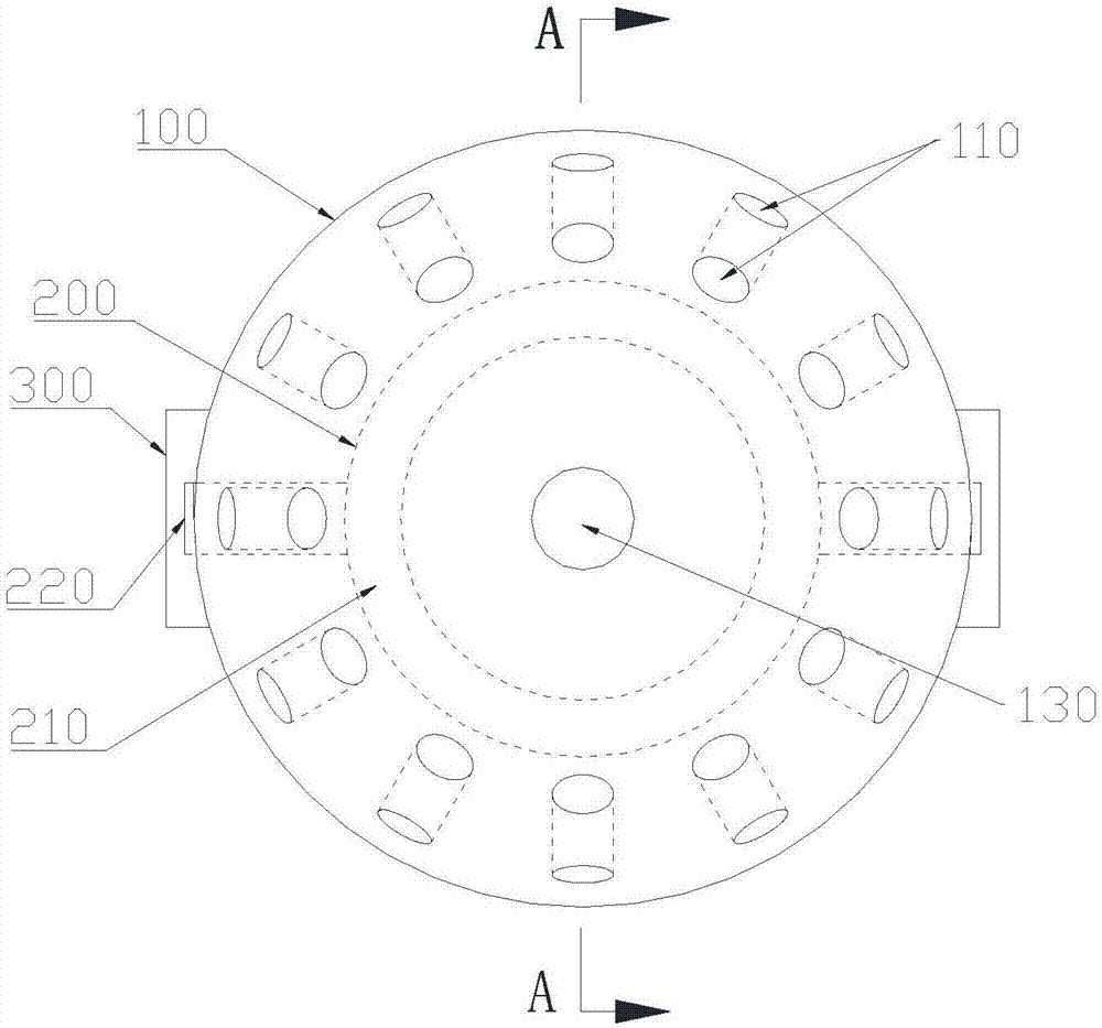
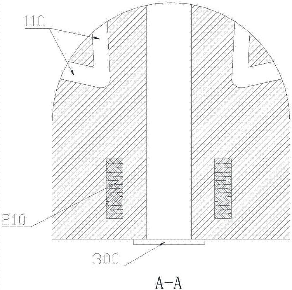
[0070] Separately communicated heat dissipation holes are provided on the adjacent surface of the edge of the inductor, and a through hole is provided coaxially with the coil main body.

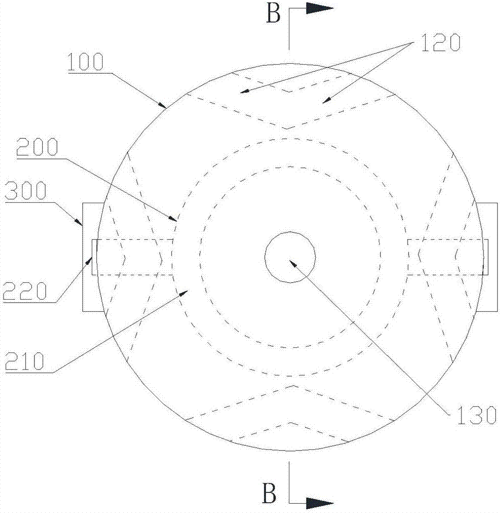
[0071] Such as Figure 5 Figure 6 As shown, the heat dissipation holes are all arranged on the adjacent planes on both sides of the edge, and as shown in Figure 5 As shown, one of the heat dissipation holes 110 at the edge is only connected to one of the heat dissipation holes 120; at the corner, one of the heat dissipation holes 110 can be connected to one or two of the heat dissipation holes 120 to form a stove similar to ventilation structure. Such as Figure 6 As shown, the heat dissipation holes 110 and the heat dissipation holes 120 are vertically arranged. This setting method is mainly aimed at small inductors. The setting method is simple and easy to operate. It can be directly drilled with a short-distance drill. Wherein, the ventilation area or cross-sectional shape of the co...

Embodiment 2

[0074] Compared with the above-mentioned first embodiment, the difference of the second embodiment is that a common communication cooling hole is provided on the adjacent surface at the edge of the inductor.

[0075] Such as Figure 7 Figure 8 As shown, the heat dissipation holes are all arranged on adjacent planes on both sides of the edge, and at the edge, one heat dissipation hole 110 communicates with multiple or all of the heat dissipation holes 120 and the heat dissipation holes 110 to form a similar It is based on the ventilation structure of the "stove". This setting method is simple and easy to operate, and can be formed by directly drilling with a drill bit.

[0076] In addition, on the one hand, such an arrangement can make the various heat dissipation holes communicate with each other, so that the surrounding air can be used to cool the places with high heat generation, and the uniformity of heat dissipation of the inductor can be improved; on the other hand, in t...

Embodiment 3

[0078] Compared with the above-mentioned second embodiment, the difference of the third embodiment is that a common communication cooling hole is provided on the adjacent surface at the edge of the inductor and the outer surface of the prism.

[0079] Such as Figure 9 Figure 10 As shown, the outer surface of the prism is covered with the heat dissipation holes, and each of the heat dissipation holes 110 is correspondingly connected with a plurality or all of the heat dissipation holes 120 and the heat dissipation holes 110, so as to form a stove similar to a "stove". ventilation structure. This setting method is simple and easy to operate, and can be formed by directly drilling with a drill bit.

[0080] In addition, such an arrangement can make the heat dissipation holes communicate with each other, so that the surrounding air can be used to cool the places with high heat generation, and the heat dissipation requirements of various parts of the inductor can be balanced; a...


PUM

PropertyMeasurementUnit
angleaaaaaaaaaa

Abstract

The invention provides a patch type power inductor. The patch type power inductor comprises a magnetizer, a coil and an end pole piece, wherein the coil is a flat wire coil and comprises a coil body and a coil outgoing line; an integrally formed structure is arranged between the magnetizer and the coil; the material forming the magnetizer tightly wraps the coil body; the coil outgoing line extends out of the magnetizer to form an electrode of the inductor; the end pole piece which is closely attached to the magnetizer is welded to the electrode; at least two cooling holes which are communicated with each other are formed in the magnetizer so as to form a ventilating structure; at least one through hole and / or a blind hole are / is formed in the magnetizer in the middle of the coil body along the axis of the coil body. Air can circulate in the magnetizer and take away heat, and the cooling efficiency is improved; meanwhile, the through hole and / or the blind hole increase / increases the flux leakage amount of the inductor, and the saturation resistance of the inductor is improved. The invention provides a manufacturing method of the patch type power inductor.

Description

technical field [0001] The invention relates to the field of electronic components, in particular to a patch type power inductor and a manufacturing method thereof. Background technique [0002] SMD inductors can be divided into two types: low-power inductors and high-power inductors. Low-power inductors are mainly used in video and communication (such as frequency selection circuits, oscillation circuits, etc.); high-power inductors are mainly used in DC / DC converters (such as energy storage components or LC filter components). Low-power chip inductors have three structures: wire-wound chip inductors, multi-layer chip inductors, and high-frequency chip inductors, while high-power inductors are all wire-wound structures. The existing integrated power inductors mainly have the following two shortcomings because the magnetizer and the coil are die-cast into a regular and compact whole: [0003] 1. The heat dissipation performance is not good, it is easy to age the coil and r...

Claims


Application Information

Patent Timeline
Patent Type & Authority Applications(China)
IPC IPC(8): H01F17/04H01F27/24H01F27/08H01F41/02H01F41/00
CPCH01F17/04H01F27/085H01F27/24H01F41/00H01F41/0246H01F2017/048
Inventor 何川
Owner SHENZHEN ZHENHUA FU ELECTRONICS
Why Eureka
Try Eureka