
Method and device for reducing self-absorption effect of spectrum

A self-absorption effect and self-absorption technology, applied in the field of spectral analysis, can solve the problems of weakening the plasma self-absorption effect and sacrificing the advantages of rapid detection, etc., to achieve convenient operation, improve stability, and achieve simple results

Active Publication Date: 2017-12-29
HUBEI ENG UNIV
View PDF3 Cites 6 Cited by
  • Summary
  • Abstract
  • Description
  • Claims
  • Application Information

AI Technical Summary

Problems solved by technology

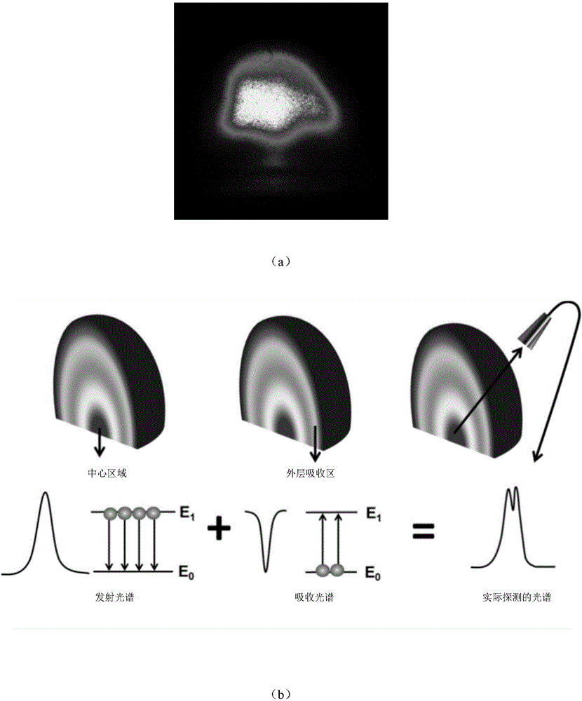
[0002] At present, domestic and foreign methods on how to reduce the self-absorption effect of Laser-induced breakdown spectroscopy (LIBS) are generally divided into two types. One is to establish a self-absorption mathematical and physical algorithm model to correct the spectrum affected by self-absorption. , but because this method analyzes and processes the self-absorption of spectral lines from the perspective of data processing in the later stage of the experiment, it can only correct the influence of self-absorption to a certain extent, which has great limitations
The other is to weaken the self-absorption effect of the plasma through a special experimental environment or device, for example, changing the ambient gas type, air pressure, mirror space constraints, etc., but this method is only suitable for element detection under special conditions, and the constructed The special environment sacrifices the rapid detection advantages of LIBS technology in the atmospheric environment

Method used


Image

  • Method and device for reducing self-absorption effect of spectrum
  • Method and device for reducing self-absorption effect of spectrum
  • Method and device for reducing self-absorption effect of spectrum

Examples


Embodiment Construction

[0038] In order to make the objectives, technical solutions, and advantages of the embodiments of the present invention clearer, the technical solutions in the embodiments of the present invention will be described clearly and completely in conjunction with the accompanying drawings in the embodiments of the present invention. Obviously, the described embodiments It is a part of the embodiments of the present invention, not all the embodiments. The components of the embodiments of the present invention generally described and illustrated in the drawings herein may be arranged and designed in various different configurations.

[0039] Therefore, the following detailed description of the embodiments of the present invention provided in the accompanying drawings is not intended to limit the scope of the claimed invention, but merely represents selected embodiments of the present invention. Based on the embodiments of the present invention, all other embodiments obtained by those of ...


PUM


Abstract

The embodiments of the invention provide a method and a device for reducing a self-absorption effect of a spectrum and are applied to an LIBS system. The method includes the steps of adjusting a defocus amount in a unit of a first preset value based on an initial defocus amount to achieve parameter traversal on a to-be-tested element in a calibration sample set, and stopping parameter traversal when the parameter satisfies a preset rule; based on the parameter, obtaining a calibration curve for quantitative analysis of the to-be-tested element in the calibration sample set under different defocus amounts; based on the calibration curve, calculating self-absorption coefficients corresponding to the to-be-tested element under different defocus amounts and saving; selecting the maximum one of the self-absorption coefficients, and using the defocus amount corresponding to the maximum one as the optimal parameter for reducing the self-absorption effect. According to the method and the device, provided by the invention, parameter traversal is realized by adjusting the defocus amount, and the parameters corresponding to the optimal self-absorption effect of the spectrum are calculated and selected according to a traversal result, so as to obtain a thin and uniform plasma with low electron density at low temperature.

Description

Technical field [0001] The present invention relates to the technical field of spectral analysis, and in particular to a method and device for reducing the self-absorption effect of the spectrum. Background technique [0002] At present, there are two methods for reducing the self-absorption effect of laser-induced breakdown spectroscopy (LIBS) at home and abroad. One is to establish a self-absorption mathematical and physical algorithm model to correct the spectrum affected by self-absorption. However, since this method analyzes and processes the self-absorption of the spectral line from the perspective of data processing in the later stage of the experiment, it can only correct the effect of self-absorption to a certain extent, which has great limitations. The other is to reduce the self-absorption effect of plasma through special experimental environments or devices, such as changing the type of ambient gas, pressure, and space constraints of the reflector, but this method is ...

Claims


Application Information

Patent Timeline
Patent Type & Authority Applications(China)
IPC IPC(8): G01N21/63
CPCG01N21/63
Inventor 曾庆栋余华清童菊芳王波云熊良斌肖永军宣文静张珍云吕昊丁么明
Owner HUBEI ENG UNIV
Learn More