Vacuum ultraviolet light source structure

A technology of vacuum ultraviolet light source and lamp tube, which is applied to the components of gas discharge lamps, climate sustainability, and sustainable buildings. Lifespan, increase vacuum ultraviolet photon number, and avoid deposition effects

Active Publication Date: 2022-06-03
PLA PEOPLES LIBERATION ARMY OF CHINA STRATEGIC SUPPORT FORCE AEROSPACE ENG UNIV
View PDF4 Cites 0 Cited by
  • Summary
  • Abstract
  • Description
  • Claims
  • Application Information

AI Technical Summary

Problems solved by technology

[0005] The purpose of the present invention is to solve the problem of insufficient output photon number and short life of the light source of the gas discharge lamp

Method used


Image

  • Vacuum ultraviolet light source structure
  • Vacuum ultraviolet light source structure
  • Vacuum ultraviolet light source structure

Examples


Embodiment Construction

[0022] The specific embodiments of the present invention will be described in detail below with reference to the accompanying drawings.

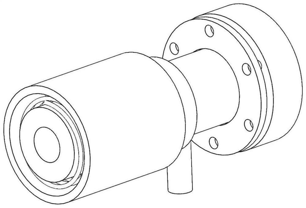
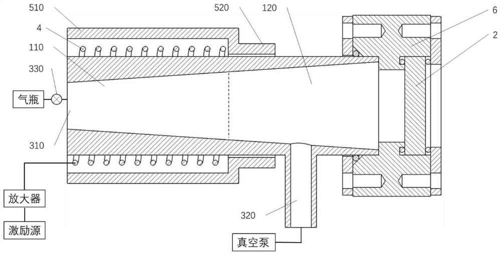
[0023] like figure 1 and figure 2 As shown in the figure, a vacuum ultraviolet light source structure designed by the present invention includes a conical lamp tube, a gas cylinder, a gas circulation pipeline, an excitation source, an amplifier, a coil 4, a shielding layer 5, a light-transmitting window 2, and a flange 6 . The excitation source is connected to the coil 4 after passing through the amplifier, the coil 4 surrounds part of the conical lamp tube, and the shielding layer 5 surrounds the coil. The conical lamp tube is divided into a discharge area 110 and an enhancement area 120. The front section of the conical lamp tube and the part surrounded by the coil 4 are the discharge area, and the rear section of the conical lamp tube and the part not surrounded by the coil 4 are the enhancement area. The inner diameter gradually incr...


PUM


Abstract

The invention discloses a vacuum ultraviolet light source structure which comprises a conical lamp tube, a gas cylinder, a gas circulation pipeline, an excitation source, an amplifier, a coil (4), a shielding layer (5), a light transmission window sheet (2) and a flange (6). Through the partition structure design of the conical lamp tube, the air pressure at the tail end of the lamp tube is reduced on the premise of ensuring the discharge air pressure so as to weaken the self-absorption effect of gas atoms, and through the design of gas circulation, a pressure gradient from high pressure to low pressure is formed in the conical lamp tube, so that the self-absorption effect of the gas atoms can be weakened; the number of output vacuum ultraviolet photons is increased, pollutants generated in a discharge area can be taken away in time, the pollutants are prevented from being deposited on the light passing window piece, and the service life of a light source is prolonged.

Description

technical field [0001] The invention relates to a light source structure, in particular to a vacuum ultraviolet light source. Background technique [0002] The photon energy of vacuum ultraviolet light is high. After absorbing a vacuum ultraviolet photon, the molecule can be excited to a higher electronic state. There is a complex interaction between the molecules in the higher electronic excited state, and direct dissociation and predissociation occur. It has a wide range of applications in the fields of photochemistry and analytical chemistry. [0003] The gas discharge lamp excites gas atoms to a high energy level through discharge, and when the atoms transition from a high energy level to a low energy level, vacuum ultraviolet light with characteristic spectral lines can be generated. At present, gas discharge lamps mainly have two problems: insufficient number of output photons and short lifespan of the light source. [0004] The reason for the insufficient number of ...

Claims


Application Information

Patent Timeline
Patent Type & Authority Applications(China)
IPC IPC(8): H01J61/33H01J61/24H01J61/26
CPCH01J61/33H01J61/24H01J61/26Y02B20/00
Inventor 冯高平洪延姬梁健玮饶伟宋俊玲王殿恺叶继飞文明
Owner PLA PEOPLES LIBERATION ARMY OF CHINA STRATEGIC SUPPORT FORCE AEROSPACE ENG UNIV
Why Eureka
Try Eureka