3D-3C particle image velocity measurement system and method based on integrated imaging technology

A particle image velocimetry and integrated imaging technology, which is applied in measuring devices, fluid velocity measurement, velocity/acceleration/impact measurement, etc., can solve the problem that it is difficult to display the details of the flow field in the particle field, limit the accuracy of three-dimensional particle image velocimetry, and affect the particle size. field reconstruction accuracy and other issues to achieve the effect of avoiding slender deformed tracer particles, improving flow field reconstruction accuracy, and fast calculation speed

Active Publication Date: 2017-12-29
NANJING UNIV OF SCI & TECH
View PDF5 Cites 14 Cited by
  • Summary
  • Abstract
  • Description
  • Claims
  • Application Information

AI Technical Summary

Problems solved by technology

The above-mentioned flow field measurement techniques have good results in the measurement of small-scale local flow field structures, but their overall visible depth is small. The maximum visible depth in the current technology is about 3 cm, but this is not the case for large-scale flow fields in the depth direction. In the measurement of flow fields such as eddy current and multi-vortex interference, it is far from enough
In addition, when the existing 3D-3C particle image velocimetry system is in a high-concentration tracer particle environment, when the tracer particles are observed from different angles, the particles will be blocked back and forth. Field reconstruction accuracy, and when the concentration of tracer particles is small, the reconstructed particle field is difficult to display the details of the flow field, which means that the corresponding spatial resolution is very limited. In addition, if the camera shooting angle is small , may cause the reconstructed tracer particles to be elongated, which seriously limits the accuracy of 3D particle image velocimetry

Method used


Image

  • 3D-3C particle image velocity measurement system and method based on integrated imaging technology
  • 3D-3C particle image velocity measurement system and method based on integrated imaging technology
  • 3D-3C particle image velocity measurement system and method based on integrated imaging technology

Examples


Embodiment Construction

[0031] The 3D-3C particle image velocimetry system and method based on the integrated imaging technology of the present invention include:

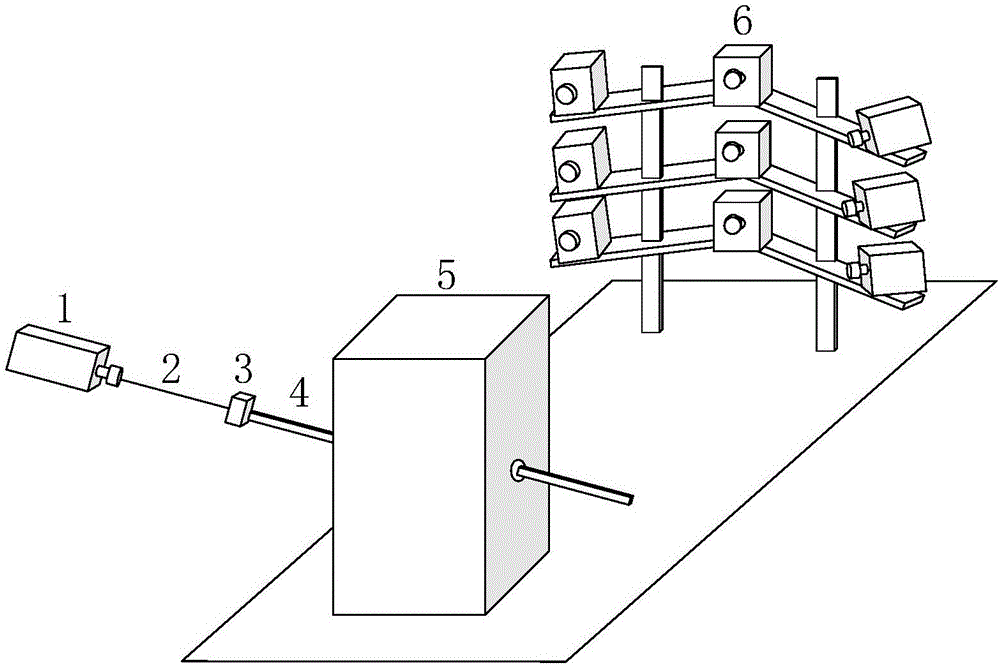
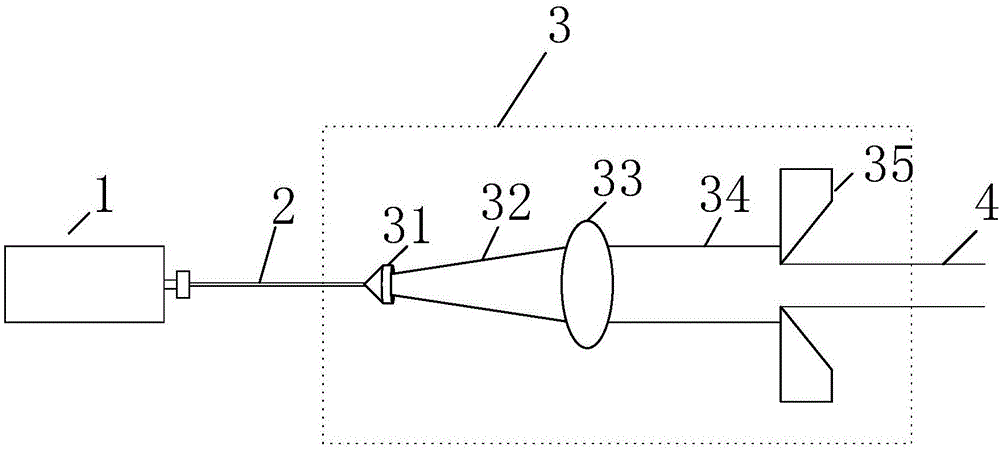
[0032] 1) For the stereoscopic lighting part, a beam of laser light emitted from the laser is expanded through a Powell prism and a cylindrical lens, and then shaped by a knife edge to form a parallel three-dimensional stereoscopic light. The stereoscopic light is irradiated into the flow field to be measured, and the three-dimensional Illumination of the pre-spread tracer particles in the flow field velocimeter.

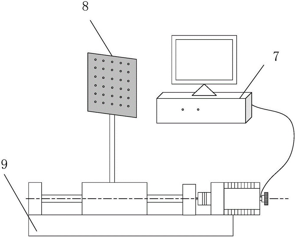
[0033] 2) The image acquisition part, according to the integrated imaging principle, adopts multiple CCD cameras arranged in an arc to form a camera array. All cameras are focused on the central area of ​​the test field, and the test field is located in the center of the camera image. This method can effectively suppress tracer particles slimming. Through computer control, the trigger board is used to generate a trigger signal...


PUM


Abstract

The invention discloses a 3D-3C particle image velocity measurement system and method based on an integrated imaging technology. The system includes a laser, a laser beam expansion and collimation system, a 3D flow field velocity measurement box, a camera array, a computer, a plane calibration board, and a precision electronic control translation table. The method includes the following steps: putting the plane calibration board in the 3D flow field velocity measurement box to calibrate the camera array; putting a tracer particle in the 3D flow field velocity measurement box, and using the camera array to image the tracer particle at different angles; re-projecting a camera image of the camera array on a known plane in a world coordinate system Z to produce a refocus image; getting a refocus image sequence by changing the Z value at equal intervals, discretizing the refocus image sequence, and saving the gray values to discrete grids; and extracting tracer particle points in different depth regions through a method based on gradient transform of a moving window, determining the positions of the tracer particle points, and reconstructing a tracer particle field. The system and the method have the advantages of high precision and high computation speed, and can be used to highly restore the details of a flow field.

Description

technical field [0001] The invention relates to the technical field of flow field optical test systems, in particular to a 3D-3C particle image velocity measurement system and method based on integrated imaging technology. Background technique [0002] Three-dimensional three-component (3D-3C) particle image velocimetry is an advanced flow field optical testing technology, which calculates the transient three-dimensional Flow field structure and flow trend can be used to measure three-dimensional complex flow fields such as turbulent flow, large-scale, multi-vortex interference, such as the flow field disturbance around the propeller when the helicopter ascends, the air disturbance generated by the bee colony flight, etc. . Currently, there are a variety of 3D-3C flow field measurement methods, such as Tomographic Particle Image Velocimetry, Holographic Particle Image Velocimetry, and Defocusing Particle Image Velocimetry. . The above-mentioned flow field measurement tech...

Claims


Application Information

Patent Timeline
Patent Type & Authority Applications(China)
IPC IPC(8): G01P5/20
CPCG01P5/20
Inventor 宋旸渠向举张芬金莹李振华纪运景许亮
Owner NANJING UNIV OF SCI & TECH
Why Eureka
Try Eureka