Automatic membrane coating technical process of battery pole group

A technology of battery pole group and process flow, applied in the construction of secondary batteries, lead-acid batteries, lead-acid batteries, etc., can solve the problems of slow PVC film, damage to the health of workers, and increase of side pushing processes, so as to achieve work efficiency High, ingenious structure, to avoid the effect of clutter

Active Publication Date: 2017-12-29
创谱(长兴)新能源科技有限公司
View PDF5 Cites 3 Cited by
  • Summary
  • Abstract
  • Description
  • Claims
  • Application Information

AI Technical Summary

Problems solved by technology

[0004] In view of the above problems, the present invention provides an automatic coating process for battery pole groups. Compared with the traditional coating process, the side push process, film feeding process, film cutting process and film coating process are added, and the PVC film is applied to the pole group. Automatic coating solves the technical problem of slow manual coating of PVC film, realizes the automation of PVC film coating, improves the working efficiency of Jiqun coating, and reduces the damage to the health of staff

Method used


Image

  • Automatic membrane coating technical process of battery pole group
  • Automatic membrane coating technical process of battery pole group
  • Automatic membrane coating technical process of battery pole group

Examples


Embodiment 1

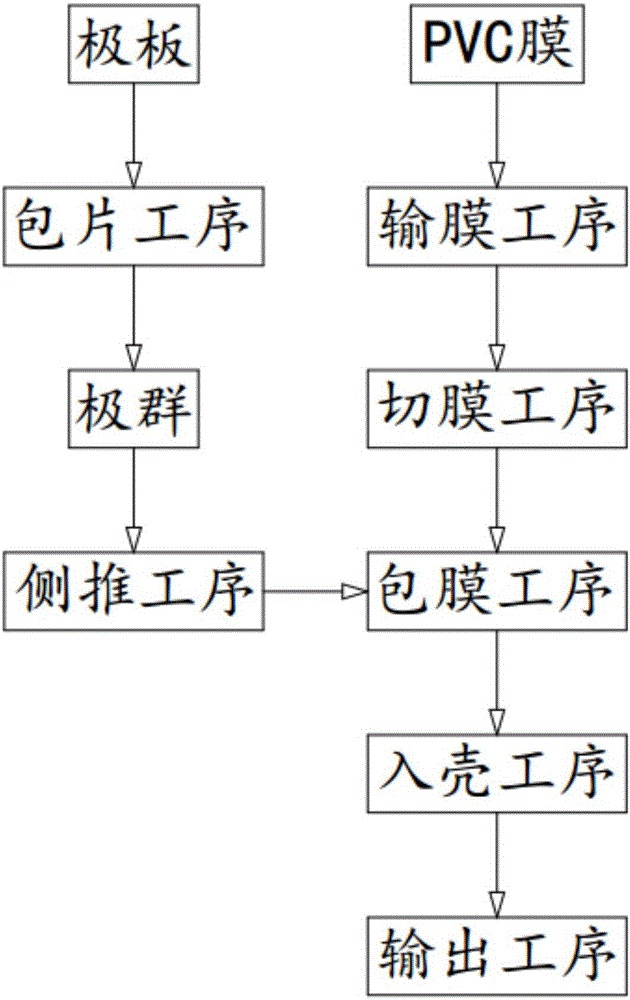
[0045] Such as figure 1 As shown, a battery electrode group automatic coating process, including:

[0046] Step 1, the wrapping process, the wrapping machine 1 stacks the positive and negative plates in sequence, and inserts separator paper between the positive and negative plates to form an electrode group 10, and the electrode group 10 is formed by the conveying channel 12 one by one. sequential delivery;

[0047] Step 2, the side pushing process, the pole group 10 conveyed by the conveying channel 12 is transported to the side pushing station at the end of the conveying channel 12, and the first cylinder 21 vertically arranged to the conveying channel 12 Pushing sideways to push the pole group 10 out of the conveying channel 12;

[0048] Step 3, film delivery process, after the pole group 10 is pushed laterally by the first cylinder 21 onto the carrying roller 33 located on one side of the conveying channel 12, the third cylinder 451 drives the PVC through the second vacu...

Embodiment 2

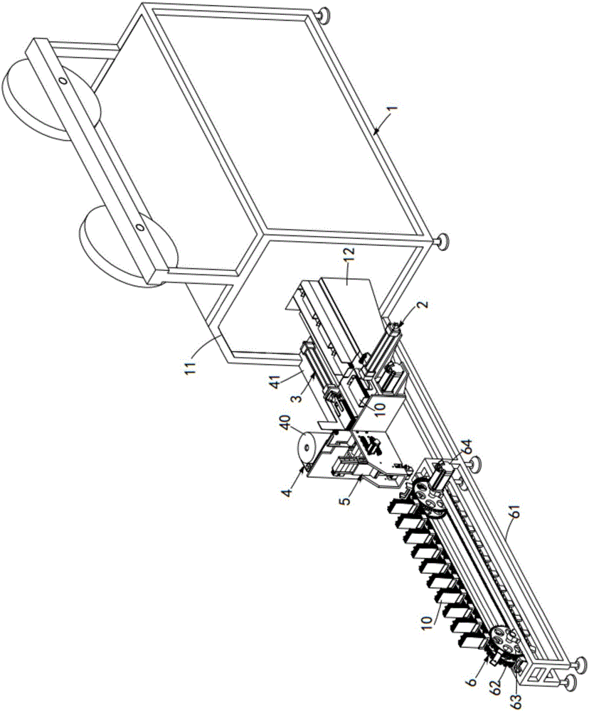
[0063] Reference manual attached figure 1 An automatic coating machine for electrode groups of lead-acid batteries according to the second embodiment of the present invention is described.

[0064] Such as figure 2 and image 3 As shown, an automatic lead-acid battery pole group coating machine includes a wrapping machine 1. The wrapping machine 1 includes a body 11 and a conveying channel 12, and several pole groups 10 are transported on the conveying channel 12, and also includes:

[0065] The first pushing mechanism 2, the first pushing mechanism 2 is arranged on one side at the end of the delivery channel 12, it is vertically arranged with the delivery channel 12, and it pushes the pole group output by the delivery channel 12;

[0066] The second pushing mechanism 3, the second pushing mechanism 3 is arranged on the other side of the conveying channel 12 relative to the first pushing mechanism 2, it is arranged in parallel with the conveying channel 12, and it pushes th...


PUM


Abstract

The invention provides an automatic membrane coating technical process of a battery pole group and aim at solving the technical problem that manual PVC (polyvinyl chloride) membrane coating of the pole group is slow. The technical process comprises a sheet coating procedure, a side pushing procedure, a membrane conveying procedure, a membrane cutting procedure, a membrane coating procedure, a shell entry procedure and an output procedure. Compared with the traditional membrane coating technology, the side pushing procedure, the membrane conveying procedure, the membrane cutting procedure and the membrane coating procedure are added; automatic PVC membrane coating is performed on the pole group; the automation of the PVC membrane coating of the pole group is achieved; the working efficiency of the membrane coating of the pole group is improved; and at the same time, the physical health damage to a worker is reduced.

Description

technical field [0001] The invention relates to the technical field of PVC coating during the processing of lead storage battery pole groups, in particular to an automatic coating process for battery pole groups. Background technique [0002] In the production process of valve-regulated sealed lead-acid batteries, the arranged electrode groups are respectively installed into the fixture according to the correct polarity, and after welding in the fixture, they are subpackaged into the battery case again. During the installation process, there will often be problems such as scratches on the side plates and high pressure resistance of the plates, which will cause loose paste on the plates, bending of the positive and negative tabs, and damage to the separator, which will eventually lead to battery failure. , in order to avoid these problems during sub-packaging, the usual measures are to reduce the thickness of the separator and reduce the assembly pressure, but this will cause...

Claims


Application Information

Patent Timeline
Patent Type & Authority Applications(China)
IPC IPC(8): H01M10/12H01M10/14
CPCH01M10/121H01M10/14Y02E60/10Y02P70/50
Inventor 姚宋明
Owner 创谱(长兴)新能源科技有限公司
Why Eureka
Try Eureka