Small-scale sealing type permanent magnet generator for wind power generation

A permanent magnet generator, closed technology, applied in the direction of electrical components, electromechanical devices, electric components, etc., can solve the problems of lack of axial flow of air, small heat exchange area of ​​the shell, aggravated permanent magnet heating, etc. Heat exchange efficiency, ensure power output, and reduce the effect of temperature

Pending Publication Date: 2017-12-29
GUANGZHOU HKUST FOK YING TUNG RES INST
View PDF0 Cites 3 Cited by
  • Summary
  • Abstract
  • Description
  • Claims
  • Application Information

AI Technical Summary

Problems solved by technology

And there is a big problem in this way, that is: the heat of the generator is generated by the windings, stator core and rotor core of the generator, but the direct metal connection between them and the generator casing is very small, and the heat generated is mainly through Air convection is transferred to the casing; due to the low thermal conductivity of the air and the small area for heat exchange on the casing, the consequence of this cooling scheme is that the internal core temperature of the permanent magnet generator is often 20 higher than the casing when operating at full load ~40°C; especially for the permanent magnets on the rotor, even though there are slots on the rotor core for cooling the permanent magnets, the lack of axial flow of air in the slots increases the temperature of the permanent magnets; the residual magnetism of the permanent magnets , coercive force, magnetic energy product, etc. will all decrease with the increase of the temperature of the permanent magnet. When the temperature reaches 100°C, the comprehensive magnetic performance will drop rapidly, the output power will decrease, and the efficiency will decrease.

Method used


Image

  • Small-scale sealing type permanent magnet generator for wind power generation
  • Small-scale sealing type permanent magnet generator for wind power generation
  • Small-scale sealing type permanent magnet generator for wind power generation

Examples


Embodiment Construction

[0028] The preferred embodiments of the present invention will be described below with reference to the accompanying drawings. It should be understood that the preferred embodiments described herein are only used to illustrate and explain the present invention, but not to limit the present invention.

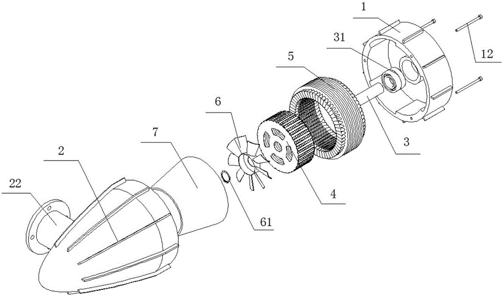
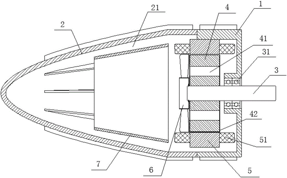
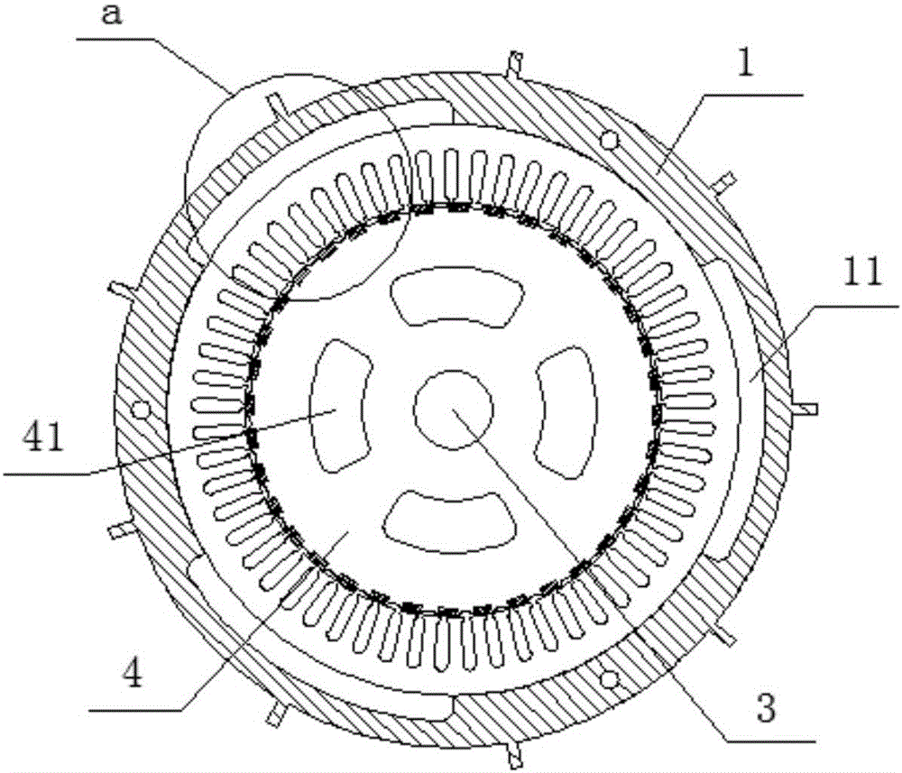
[0029] As shown in the figure, a small enclosed permanent magnet generator for wind power generation according to the present invention includes a casing, a rotor core 4, a stator core 5, a stator winding 51 and a motor shaft 3, and the casing includes a front casing 1 and rear housing 2, also including:

[0030] The heat dissipation device includes a radiator and a shroud 7. The radiator is arranged at the end of the motor shaft 3. The motor shaft 3 is also connected with the rotor core 4 and the front casing 1 in sequence. The shroud 7 corresponds to the stator winding. 51 is arranged in the described rear casing 2;

[0031] The heat dissipation channel includes the rotor coo...


PUM


Abstract

The invention discloses a small-scale sealing type permanent magnet generator for wind power generation, comprising a casing, a rotor iron core, a stator iron core, a stator winding and a motor shaft. The casing comprises a front casing and a rear casing, and also a heat radiation apparatus and a heat radiation channel. The heat radiation apparatus comprises a radiator and an air guiding sleeve. The heat radiation channel comprises a rotor cooling air channel, a permanent magnet cooling air channel, a stator cooling air channel and a rear casing heat radiation wind channel. Two end faces of the rotor iron core are respectively provided with a non-magnetic material separator plate. The invention is advantageous in that the internal structure of the permanent magnet generator can be fully utilized, heat exchange and heat radiation of heat energy in the permanent magnet generator can be effectively achieved, and thereby the magnetic comprehensive properties, the generating efficiency and quality of the permanent magnet generator can be ensured.

Description

technical field [0001] The invention belongs to the technical field of generators, and in particular relates to an enclosed permanent magnet generator for small wind power generation. Background technique [0002] The permanent magnet generator basically consists of a casing, a rotating shaft, a bearing, a rotor, a stator and a cooling fan. In order to dissipate the heat generated by copper loss and iron loss during the operation of the generator, the casing is often provided with cooling holes; however, small wind generators need to operate outdoors. In order to ensure their service life, the permanent magnet generator is required. It needs to be a closed generator, and the volume of the motor is required to be as small as possible. Since there is no heat dissipation hole, and there is not enough internal space for air convection, the cooling fan in the permanent magnet generator has no meaning in the enclosed motor. [0003] At present, the heat dissipation method adopte...

Claims


Application Information

Patent Timeline
IPC IPC(8): H02K9/14H02K9/06H02K1/32H02K1/20
CPCH02K1/20H02K1/32H02K9/06H02K9/14
Inventor 吴池力欧宝星赵汝恒张骏升陈宇明傅秀聪
Owner GUANGZHOU HKUST FOK YING TUNG RES INST
Why Eureka
Try Eureka