Dual mode fiber monitoring system which has protection optical path and whose fault can be healed by itself, and dual mode fiber monitoring method
A technology for monitoring systems and protecting optical paths, which is applied in transmission monitoring/testing/fault measurement systems, transmission systems, fault recovery arrangements, etc. It can solve the problems of low sharing of components in equipment, interruption of optical fiber communication, and high equipment costs. The effect of normal operation of communication, resolution of communication interruption, and improvement of reliability
- Summary
- Abstract
- Description
- Claims
- Application Information
AI Technical Summary
Problems solved by technology
Method used
Image
Examples
specific Embodiment approach 1
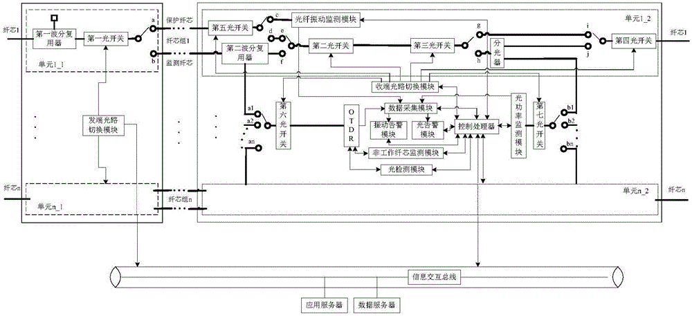
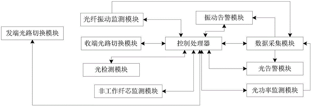
[0031] Specific implementation mode 1. Combination figure 1 with figure 2 Describe this embodiment, a dual-mode optical fiber monitoring system with protection optical path and fault self-healing, the monitoring system includes at least one monitoring unit, each monitoring unit includes a sending end monitoring subunit and a receiving end monitoring subunit, and the sending end monitoring subunit includes The first optical switch and the first wavelength division multiplexer, the receiving end monitoring subunit includes an optical fiber vibration monitoring module, a second optical switch, a third optical switch, a fourth optical switch, a fifth optical switch, and a second wavelength division multiplexer Each unit shares the control processor, data acquisition module, optical power monitoring module, non-working fiber core monitoring module, optical detection module, sending end optical path switching module, receiving end optical path switching module, optical alarm module...
specific Embodiment approach 2
[0039] Specific embodiment two, combine figure 1 with figure 2 Describe this embodiment, this embodiment is the dual-mode optical fiber monitoring method with a protected optical path and fault self-healing described in the first specific embodiment, figure 1 In , the thick black connection line represents the fiber core and optical path, and the thin black connection line represents the data connection. The system equipment is divided into n monitoring units, and the monitoring unit i includes the sending end monitoring subunit i_1 and the receiving end monitoring subunit i_2, 1≤i≤n, and the sending end monitoring subunit includes the first wavelength division multiplexer, the first optical switch , the sending end monitoring subunit 1_1, subunit 2_1...subunit n-1 share the sending end optical path switching module; the receiving end monitoring subunit includes an optical fiber vibration monitoring module, a second optical switch, a second wavelength division multiplexer, a...
PUM
 Abstract
Description
Claims
Application Information
 - R&D
- Intellectual Property
- Life Sciences
- Materials
- Tech Scout
- Unparalleled Data Quality
- Higher Quality Content
- 60% Fewer Hallucinations
Browse by: Latest US Patents, China's latest patents, Technical Efficacy Thesaurus, Application Domain, Technology Topic, Popular Technical Reports.
© 2025 PatSnap. All rights reserved.Legal|Privacy policy|Modern Slavery Act Transparency Statement|Sitemap|About US| Contact US: help@patsnap.com


