Assembling mechanism of power supply module

A power module and assembly mechanism technology, applied in the direction of electrical components, electrical components, etc., can solve the problems of no angle adjustment, troublesome operators, random placement of tools, etc., to facilitate assembly operations, speed up assembly speed, and improve assembly quality Effect

Active Publication Date: 2017-12-29
ANHUI KECHUANG NEWENERGY TECH CO LTD
View PDF4 Cites 3 Cited by
  • Summary
  • Abstract
  • Description
  • Claims
  • Application Information

AI Technical Summary

Problems solved by technology

[0003] (1) During assembly, since there is no limit device on the workbench, the operator needs to fix the circuit board by hand, and the power module parts need to be operated by hand during assembly, which is very inconvenient for the operator to fix the power module. assembly;
[0004] (2) During assembly, sometimes it is necessary to place the circuit board obliquely to complete the assembly of parts on the circuit board conveniently and quickly. However, the assembly mechanism of the existing power module does not have the function of angle adjustment, so that the inclination of the circuit board cannot be realized. This greatly reduces the assembly efficiency of the power module and brings great trouble to the operator;
[0005] (3) The existing power module assembly mechanism does not have a special place for placing the tools and parts required for assembly, so when assembling, the required tools and parts are usually placed directly on the workbench, which is easy to cause the loss of small parts , the random placement of tools is also inconvenient for the operator to use

Method used


Image

  • Assembling mechanism of power supply module
  • Assembling mechanism of power supply module
  • Assembling mechanism of power supply module

Examples


Embodiment

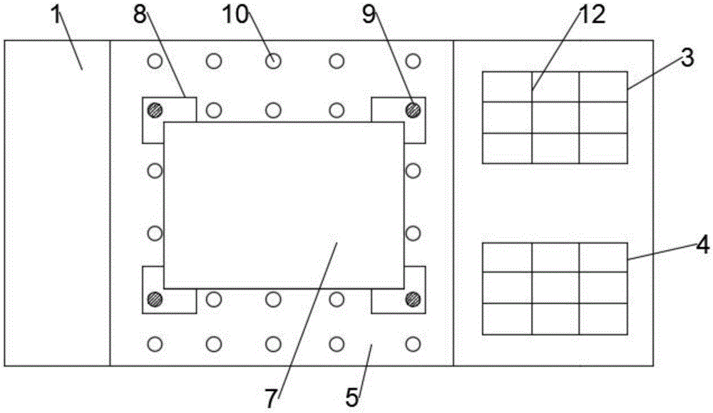
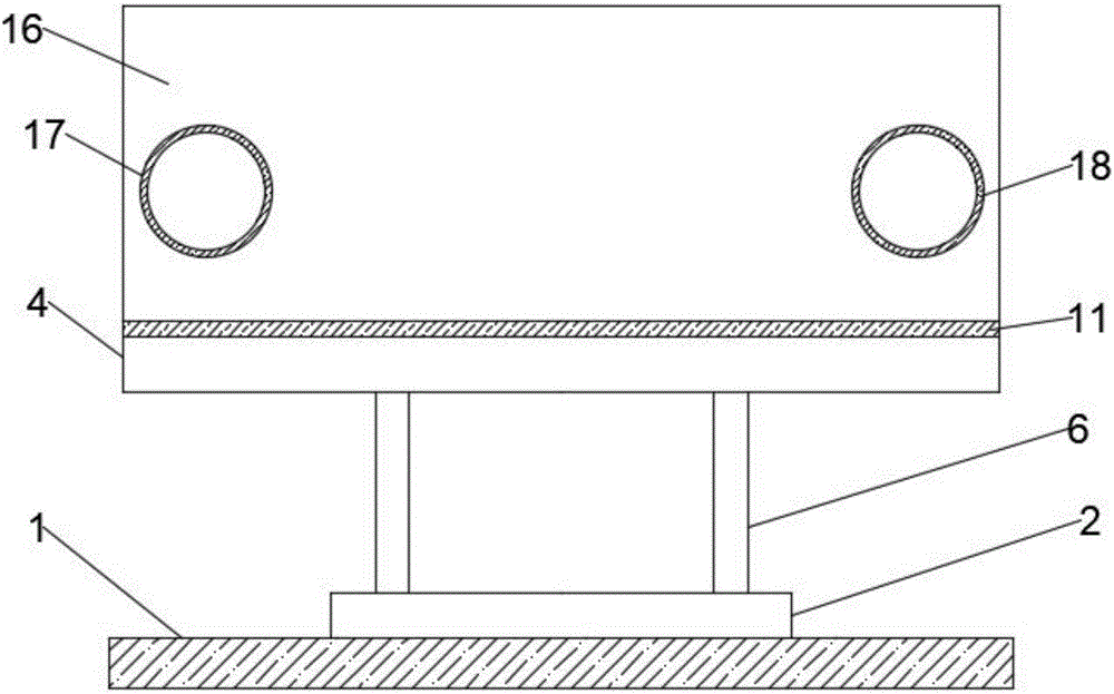
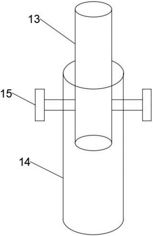
[0026] Such as figure 1 , figure 2 and image 3 As shown, the present invention discloses an assembly mechanism of a power module, including a workbench 1, a processing position 2 is provided on the upper surface of the workbench 1, a tool box 3 and a parts box 4 are arranged on the upper surface of the workbench 1 , the tool box 3 is used to place the tools used for assembling the power module, the parts box 4 is used to place the parts required for assembling the power module, and a rectangular operating panel 5 is arranged above the processing position 2, so The operation panel 5 is connected with the processing position 2 through the telescopic rod 6, and the number of the telescopic rods 6 is four. By adjusting the height of different telescopic rods 6, the function of adjusting the angle of the different positions of the operation panel 5 is realized, so that The operating panel 5 is tilted according to the requirements, which is convenient for assembly. The four tele...


PUM


Abstract

The invention discloses an assembling mechanism of a power supply module. The mechanism comprises a work bench. An upper surface of the work bench is provided with a processing position. The upper surface of the work bench is provided with a tool box and a part box. A rectangular operation plate is arranged above the processing position. The operation plate is connected to the processing position through telescoping rods. There are four telescoping rods. The four telescoping rods are arranged below a lower surface of the operation plate. Top ends of the telescoping rods are connected to the operation plate. Bottom ends of the telescoping rods are connected to the processing position. The operation plate is used to assemble the power supply module. The operation plate is provided with a circuit board and four L-shaped limit blocks. The four limit blocks are used to limit the circuit board. The four limit blocks are provided with a first threaded hole. The operation plate is provided with several second threaded holes. The four limit blocks are connected to the circuit board through screws. The structure is simple, operation is simple, an assembling function of the power supply module can be realized, and power supply module assembling efficiency is greatly increased.

Description

technical field [0001] The invention relates to the technical field of power module production, in particular to an assembly mechanism of a power module. Background technique [0002] The power module is a power supply that can be directly mounted on the printed circuit board, and its characteristic is that it can be used for application-specific integrated circuits (ASIC), digital signal processors (DSP), microprocessors, memories, field programmable gate arrays ( FPGA) and other digital or analog loads to provide power. Generally, such modules are called point-of-load (POL) power supply systems or point-of-use power supply systems (PUPS). Due to the many advantages of the modular structure, the module power supply is widely used in communication fields such as switching equipment, access equipment, mobile communication, microwave communication, optical transmission, routers, automotive electronics, aerospace, etc., the power module is used in the production and use proces...

Claims


Application Information

Patent Timeline
Patent Type & Authority Applications(China)
IPC IPC(8): H05K13/00
CPCH05K13/0015
Inventor 鹿婷婷
Owner ANHUI KECHUANG NEWENERGY TECH CO LTD
Why Eureka
Try Eureka