Teaching method for robot and robot

A teaching method and robot technology, applied in the directions of robots, instruments, manipulators, etc., can solve the problem that the position of the beam direction of the image sensor cannot be specified, and achieve the effect of improving the teaching accuracy.

Active Publication Date: 2018-01-02
KAWASAKI HEAVY IND LTD +1
View PDF7 Cites 2 Cited by
  • Summary
  • Abstract
  • Description
  • Claims
  • Application Information

AI Technical Summary

Problems solved by technology

Therefore, the position in the beam direction of the image sensor cannot be specified

Method used


Image

  • Teaching method for robot and robot
  • Teaching method for robot and robot
  • Teaching method for robot and robot

Examples


Embodiment Construction

[0036] (first embodiment)

[0037] Hereinafter, a first embodiment of the present invention will be described with reference to the drawings. Hereinafter, the same reference numerals are attached to the same or corresponding elements in all the drawings, and repeated explanations are omitted.

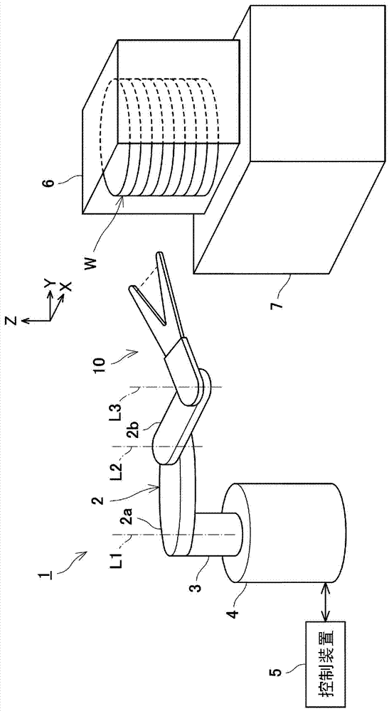
[0038] figure 1 It is a schematic diagram showing the structure of the robot 1 of the first embodiment. like figure 1 As shown, the robot 1 is used, for example, to transport a substrate W such as a wafer, which is a material of a semiconductor package, in a semiconductor processing facility for manufacturing a semiconductor package. Wafers include semiconductor wafers and glass wafers. Semiconductor wafers include, for example, silicon wafers, wafers of other semiconductor monomers, and wafers of compound semiconductors. Glass wafers include, for example, glass substrates for FPDs, glass substrates for MEMS, and sapphire (single crystal alumina) wafers. A semiconductor processing...


PUM


Abstract

This teaching method for robot includes: a shaking step for shaking a hand around a prescribed revolving axis on an axis perpendicular to an optical axis of a sensor beam such that a target is scannedin a horizontal direction by the sensor beam; a determining step for determining whether the target matches a position along the central axis in the longitudinal direction of the hand on the basis ofa detection signal of a mapping sensor (12), which varies due to the shaking of the hand; and a shift step for calculating an offset amount of the hand on the basis of the detection signal of the mapping sensor, which varies due to the shaking of the hand, when the target is determined not to match the position, and for shifting, according to the calculated offset amount, the hand in any one of the left and right directions along the optical axis of the sensor beam.

Description

technical field [0001] The invention relates to a robot teaching method and the robot. Background technique [0002] In general, when transporting semiconductor wafers, glass substrates for display panels, etc. in semiconductor processing equipment, a horizontal articulated transfer robot with a link system is used. In some cases, a mapping sensor (mapping sensor) is provided at the tip of the hand of the transfer robot. The image sensor is used to detect whether the substrate is stored in the cassette. For example, the image sensor is configured such that the sensing light beam advances linearly in the space between the first and second tips of the bifurcated hand. Generally speaking, when an image sensor is used to detect an object, the detection position is the position where the object blocks the sensing beam. Therefore, the position in the beam direction of the image sensor cannot be specified. As a prior art, U.S. Patent No. 752,267 discloses a technique for calcul...

Claims


Application Information

Patent Timeline
IPC IPC(8): B25J9/06B25J15/08
CPCB25J9/1612G05B2219/37415G05B2219/39536G05B2219/45057Y10S901/47Y10S901/03B25J9/163B25J9/1697H01L21/67259H01L21/681
Inventor 中矢敦史山口隆生中原一陈甘源
Owner KAWASAKI HEAVY IND LTD
Why Eureka
Try Eureka