Systems and methods for current limiting

A current limiting and current technology, applied in the direction of control/regulation system, power supply test, electrical components, etc.

Active Publication Date: 2021-06-08
HEWLETT-PACKARD ENTERPRISE DEV LP
View PDF7 Cites 0 Cited by
  • Summary
  • Abstract
  • Description
  • Claims
  • Application Information

AI Technical Summary

Problems solved by technology

Power flow from the source to the load may be interrupted, for example due to a source failure, a source reverse flow failure, scheduled repair or replacement of the source, etc.

Method used


Image

  • Systems and methods for current limiting
  • Systems and methods for current limiting
  • Systems and methods for current limiting

Examples


Embodiment Construction

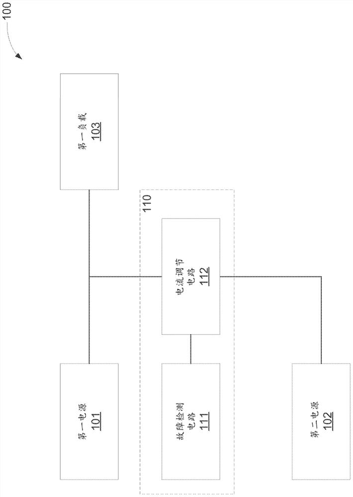
[0016] The voltage output of the power supply may drop significantly before the fault detection circuit detects a power supply failure. For example, the power supply may be an alternating current (AC) to direct current (DC) converter that includes a pulsating voltage at the output, so the fault detection circuit may wait for the voltage to drop enough for the fault detection circuit to determine that it is detecting a power failure rather than just Just a pulsation. The backup power source may be electrically connected to the load by activating a switch or otherwise in response to detecting a power failure. Due to the significant voltage drop, large currents may flow from the backup power source through the switch when the backup power source is initially connected to the load. For example, the load may include a large parallel capacitance, or may have a large capacitance in parallel with the load. When the switch electrically connects the bulk capacitor to the backup power ...


PUM


Abstract

An example system includes a first power source. The system also includes a first load electrically connected to the first power source. The system also includes a second power source. The system further includes fault mitigation circuitry. A fault mitigation circuit is used to detect a fault of the first power supply. A fault mitigation circuit is for electrically connecting the second power source to the first load in response to detecting a fault. The fault mitigation circuit is for limiting current flow from the second power source through the fault mitigation circuit.

Description

technical field [0001] The present disclosure generally relates to current limiting. Background technique [0002] A power supply can deliver power to a load. For example, a power source and a load may be electrically connected through a high potential rail and a low potential rail. Power flow from a power source to a load may be interrupted, for example, due to a power source failure, a power reverse flow failure, scheduled repair or replacement of the power source, and the like. A backup power source may be electrically connected to the load to provide power to the load until the fault is corrected or the repair is completed. Contents of the invention [0003] Therefore, according to one aspect of the present disclosure, the present disclosure proposes a system for current limiting, comprising: a fault detection circuit for: detecting a fault of a first power supply electrically connected to a first load, and outputting an indication of the detected a first signal of ...

Claims


Application Information

Patent Timeline
IPC IPC(8): H02J1/10H02J3/06H02J3/24H02J9/06H02J9/00G01R31/40
CPCH02J9/061G01R31/40H02J3/06H02J9/00H02J1/10G05F1/44
Inventor 丹尼尔·汉弗莱迈克尔·德拉尼穆罕默德·阿明·贝马特
Owner HEWLETT-PACKARD ENTERPRISE DEV LP
Why Eureka
Try Eureka