
Machining device and method for hard alloy valve element of throttle valve

A technology of cemented carbide and processing device, applied in the field of cemented carbide, can solve the problems that the valve core structure cannot be used, the hollow cylinder is difficult to achieve anti-scour, and the small holes cannot be machined, so as to reduce the processing difficulty and avoid clamping The effect of preventing damage and saving processing time

Active Publication Date: 2018-01-05
SOUTHWEST PETROLEUM UNIV
View PDF6 Cites 2 Cited by
  • Summary
  • Abstract
  • Description
  • Claims
  • Application Information

AI Technical Summary

Problems solved by technology

[0004] At present, there is a certain amount of research on double-layer cemented carbide structures at home and abroad, such as the Chinese patent (application number 201110374632.0) "A Particle Immersion Casting Method for Preparing Cemented Carbide / Steel Laminated Composite Materials", the method used is The steel ball is placed inside, and then the valve cover is made of hard alloy on the outside. The ball processed in this way can meet the wear requirements, but it is difficult to achieve the anti-scouring effect on the hollow cylinder, and the hollow cylinder cannot use the same The way to process, let alone the small holes on it
Chinese Patent (Application No. 201310724238.4) "Double-Layer Cemented Carbide Substrate and Its Preparation Method" proposes to preform the outer layer of cemented carbide into a U shape, and then use it as a container to place the inner layer of cemented carbide And sintering, but this method can only make solid carbide with U-shaped structure, and cannot be used for the manufacture of valve core structure

Method used


Image

  • Machining device and method for hard alloy valve element of throttle valve
  • Machining device and method for hard alloy valve element of throttle valve
  • Machining device and method for hard alloy valve element of throttle valve

Examples


Embodiment Construction

[0048] The present invention will be further described below in conjunction with the accompanying drawings and embodiments.

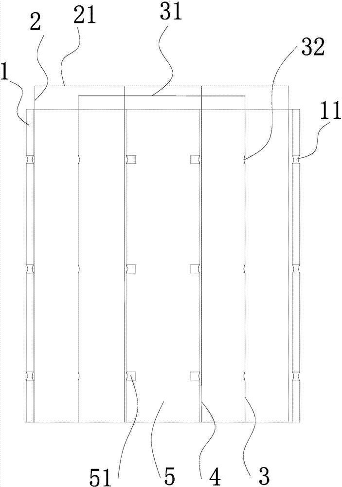
[0049] Such as Figure 1-13 As shown, a processing device for a hard alloy valve core of a throttle valve consists of an outer cover 1, an outer leak-proof plate 2, a partition 3, an inner cover 5, an inner cover leak-proof plate 4, a punching rod 6, The working box 7, the lower extrusion block 9, and the upper extrusion block 8 are composed; on the lower extrusion block 9, the outer casing 1, the outer casing leak-proof plate 2, the partition 3, the inner casing 5, and the inner casing leak-proof plate are placed in sequence from outside to inside 4. The upper extrusion block 8 is aligned with the axis of the inner sleeve 5 and arranged above the inner sleeve 5; the outer sleeve 1 is a hollow cylinder with a height of 150 mm and an inner diameter of 60 mm; the inner sleeve 5 is a solid cylinder with a height of 150 mm , the outer diameter is 45mm; the...


PUM

PropertyMeasurementUnit
heightaaaaaaaaaa
heightaaaaaaaaaa
thicknessaaaaaaaaaa

Abstract

The invention provides a machining device and method for a hard alloy valve element of a throttle valve. The machining device is composed of an outer sleeve, an outer sleeve leakage-proof plate, a partition plate, an inner sleeve, an inner sleeve leakage-proof plate, a punching rod, a working box, a lower squeezing block and an upper squeezing block. The outer sleeve, the outer sleeve leakage-proof plate, the partition plate, the inner sleeve and the inner sleeve leakage-proof plate are sequentially placed on the lower squeezing block from outside to inside, the upper squeezing block is aligned with the axis of the inner sleeve and arranged above the inner sleeve, the working box is a thermal insulation box body, and a base is arranged below the interior of the working box; the lower squeezing block is installed in the middle of the base, a hand grab telescopic rod is arranged on the side face of the base, a hand grab extending to the position above the lower squeezing block is arranged at the top end of the hand grab telescopic rod, and a sliding rail is arranged at the top of the working box; and an upper squeezing block telescopic rod is installed below the sliding rail, the upper squeezing block telescopic rod can slide along the sliding rail, and the lower portion of the upper squeezing block telescopic rod is connected with the upper squeezing block. According to the design of the machining device and method adapting to the hard alloy valve element of the throttle valve, the purpose that a double-layer hard alloy valve element is manufactured is achieved.

Description

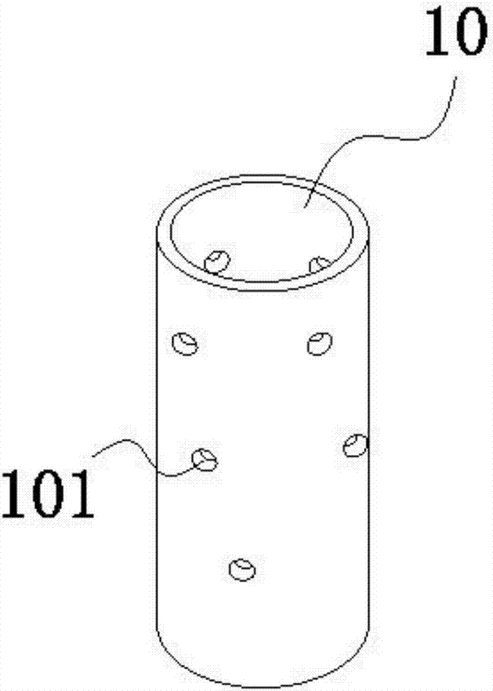
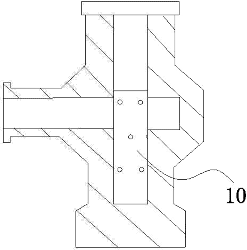
technical field [0001] The invention relates to the technical field of hard alloys, in particular to a processing device and method for a hard alloy valve core of a throttle valve. Background technique [0002] During the production of natural gas wells, it is necessary to install throttle valves on gas production wellheads, various manifolds and other high-pressure pipelines to adjust the flow rate of natural gas production. The core component of the throttle valve is the spool. By setting a number of small holes on the spool and adjusting the position of the spool in the flow channel, the purpose of adjusting the flow is achieved. At present, a certain throttle valve used in an oil field in China The spool has a structure such as figure 1 As shown, the hollow tubular structure is composed of cemented carbide (the main components are WC and Co), and there are a number of small holes arranged in a spiral shape on it. The installation method of the throttle valve is as follo...

Claims


Application Information

Patent Timeline
Patent Type & Authority Applications(China)
IPC IPC(8): B22F3/03B22F3/10B22F3/24B22F5/10C22C29/08
CPCY02T10/12
Inventor 冯春宇王胜军周建李悦钦梁栋
Owner SOUTHWEST PETROLEUM UNIV
Learn More