Automatic machine tool scrap iron cleaning device

An automatic cleaning and iron filing technology, applied in metal processing machinery parts, maintenance and safety accessories, metal processing equipment, etc., can solve problems such as affecting production safety and production efficiency, waste of human resources, and inability to achieve clean production in sanitary conditions. To achieve the effect of convenient, fast and safe collection and avoid iron filings flying around

Inactive Publication Date: 2018-01-05
陈伟江
View PDF0 Cites 4 Cited by
  • Summary
  • Abstract
  • Description
  • Claims
  • Application Information

AI Technical Summary

Problems solved by technology

[0002] Computer numerical control machine tools are famous for their high machining accuracy and high machining efficiency, but a lot of iron filings are produced during the machining process. For these iron filings, the traditional method is still used at present, that is, to let the iron filings continue to accumulate until the end of get off work The operator of the machine tool takes time out to clean in advance; the operator of the machine tool uses a high-pressure air gun to blow the debris and dirt on the surface of the parts, so that the debris and dirt fly around, which not only causes pollution to the ground and the machine tool, but also has safety hidden danger, debris is easy to fly into the eyes of the operator; therefore, the existing cleaning methods will seriously affect the sanitation inside the lathe and cannot achieve clean production, and iron filings will continue to accumulate, which will affect production safety and production efficiency; and, Machine tool operators are senior machinists, and their time value is relatively high, but it is a waste of human resources to spend a lot of time in each shift to clean up iron filings

Method used


Image

  • Automatic machine tool scrap iron cleaning device

Examples


Embodiment Construction

[0012] The following will clearly and completely describe the technical solutions in the embodiments of the present invention with reference to the accompanying drawings in the embodiments of the present invention. Obviously, the described embodiments are only some, not all, embodiments of the present invention. Based on the embodiments of the present invention, all other embodiments obtained by persons of ordinary skill in the art without making creative efforts belong to the protection scope of the present invention.

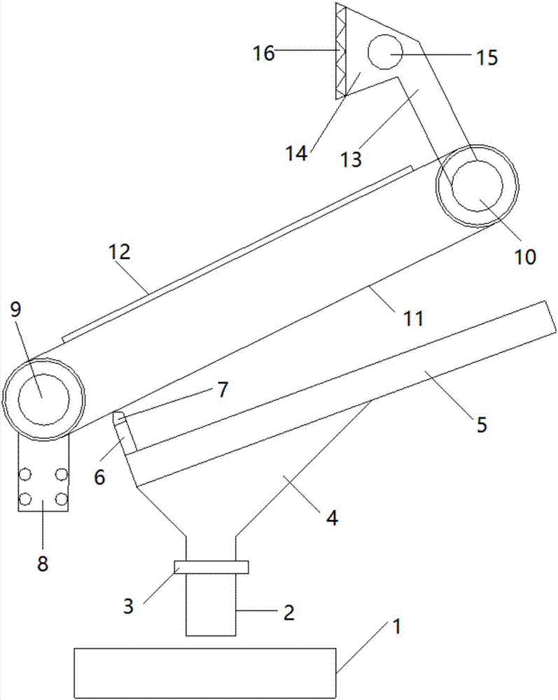
[0013] see figure 1 , the present invention provides a technical solution: comprising an iron filings collection box 1, a material collection pipe 2 is vertically arranged in the upper middle of the iron filings collection box 1, and a casing joint 3 is provided at the top of the collection pipe 2, The top of the receiving pipe 2 is connected with a collection funnel 4 through a sleeve joint 3, and the top of the collection funnel 4 is connected with a slide p...


PUM


Abstract

The invention discloses an automatic machine tool scrap iron cleaning device. The automatic machine tool scrap iron cleaning device comprises a scrap iron collection box. A collection pipe is vertically arranged on the middle portion above the scrap iron collection box. The top end of the collection pipe is provided with a sleeve joint. The top end of the collection pipe is connected with a collection funnel through the sleeve joint. The top end of the collection funnel is obliquely connected with a sliding plate. The bottom end of the upper surface of the sliding plate is provided with a scraping plate perpendicular to the sliding plate, and the top end of the scraping plate is provided with a wedge-shaped sharp corner. The automatic machine tool scrap iron cleaning device adopts the combination of a wild-mouth suction cup and a filter screen, a centrifugal fan can suck scrap iron, the scrap iron can fall onto a conveyor belt from the position of the filter screen, the risk of scrap iron flying is avoided, flexible magnetic sheets on the conveyor belt attract the scrap iron through magnetic fields, and the scrap iron is controlled easily and conveyed conveniently; and the wedge-shaped sharp corner on the scraping plate cooperates with the conveyor belt to scrape off the scrap iron, the scrap iron is guided through the sliding plate, the scrap iron passes through the collectionfunnel and the collection pipe to enter the scrap iron collection box, and convenient, rapid and safe machine tool scrap iron collection can be achieved.

Description

technical field [0001] The invention relates to the technical field of machine tool auxiliary processing equipment, in particular to an automatic cleaning device for machine tool iron filings. Background technique [0002] Computer numerical control machine tools are famous for their high machining accuracy and high machining efficiency, but a lot of iron filings are produced during the machining process. For these iron filings, the traditional method is still used at present, that is, to let the iron filings continue to accumulate until the end of get off work The operator of the machine tool takes time out to clean in advance; the operator of the machine tool uses a high-pressure air gun to blow the debris and dirt on the surface of the parts, so that the debris and dirt fly around, which not only causes pollution to the ground and the machine tool, but also has safety hidden danger, debris is easy to fly into the eyes of the operator; therefore, the existing cleaning method...

Claims


Application Information

Patent Timeline
IPC IPC(8): B23Q11/00
CPCY02P70/10
Inventor 陈伟江刘之琪
Owner 陈伟江
Why Eureka
Try Eureka