Steam generator simulation body water supply system used in heating and boosting process and control method
A steam generator and water supply system technology, applied in the direction of steam generation, water supply control, preheating, etc., can solve problems such as the complexity of the water supply system, and achieve the effect of high control progress, fast speed and simple operation process
- Summary
- Abstract
- Description
- Claims
- Application Information
AI Technical Summary
Problems solved by technology
Method used
Image
Examples
Embodiment 1
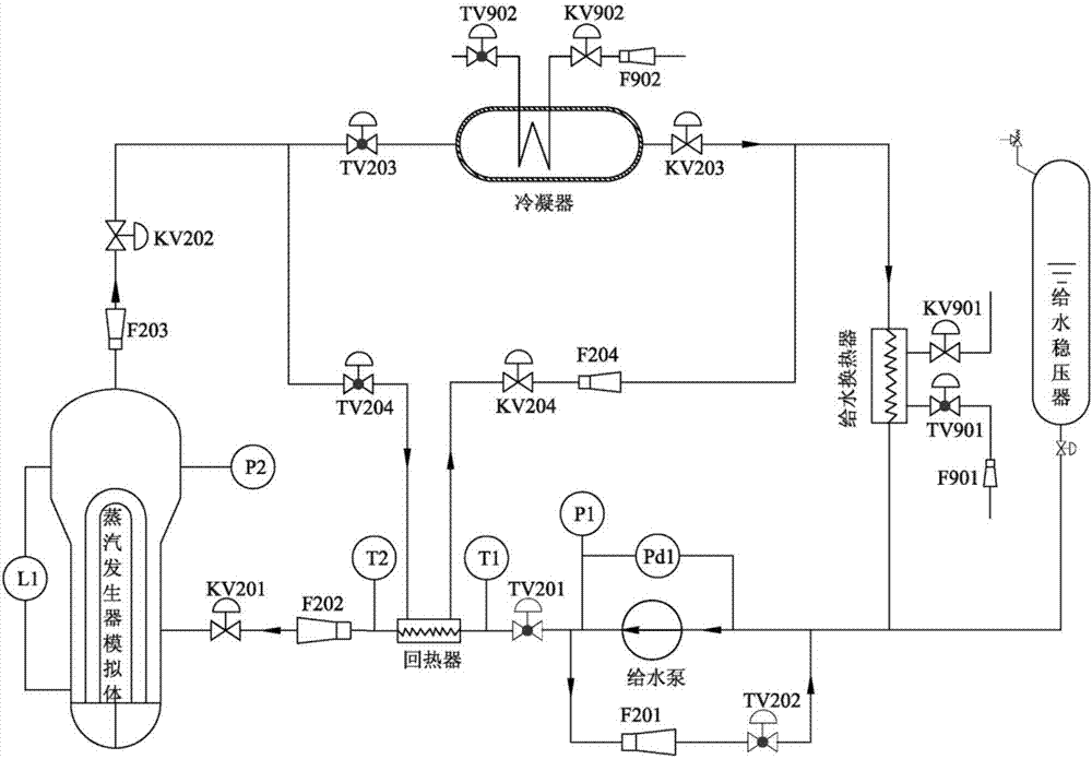
[0039] Such as figure 1 As shown, the water supply system of the steam generator simulation body in the process of temperature rise and pressure increase includes a steam generator simulation body, a feed water regulator, and a condenser. The steam generator simulation body communicates with the condenser through a steam pipeline, a feedwater pump is arranged on the water inlet pipeline, the outlet end of the condenser communicates with the inlet end of the feedwater pump through a cold water pipeline, and the cold water pipeline is provided with There is a valve KV203, the feed water pump adopts a frequency conversion multi-stage centrifugal pump, a bypass branch of the feed water pump is arranged in parallel on the water inlet pipeline, a regenerator is arranged on the rear end of the feed water pump on the water inlet pipeline, and the The outlet end of the regenerator communicates with the inlet end of the condenser, and the inlet end of the regenerator communicates with t...
Embodiment 2
[0041] Such as figure 1 As shown, this embodiment is based on Embodiment 1. A feed water heat exchanger is arranged on the cold water pipeline, and the feed water heat exchanger is arranged at the rear end of the steam side outlet of the regenerator; the feed water heat exchanger is connected to the external water supply end to form a circulation loop, the circulation loop is provided with a regulating valve TV901, a flow meter F901, and a valve KV901; a regulating valve TV204 is provided on the pipeline connecting the outlet end of the regenerator and the inlet end of the condenser, and the A flow meter F204 and a valve KV204 are arranged on the connecting pipeline between the inlet end of the regenerator and the outlet end of the condenser (on the steam side of the regenerator); the condenser and the external water supply end form a circulation loop, and the circulation loop is provided with Regulating valve TV902, flow meter F902, and valve KV902.
Embodiment 3
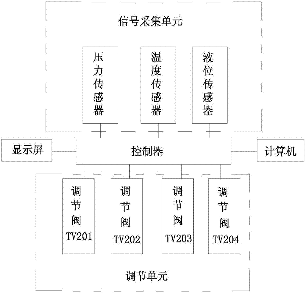
[0043] Such as figure 1 , figure 2 As shown, this embodiment is based on embodiment 1 or embodiment 2, and also includes a control system, the control system includes a control unit, a signal acquisition unit and an adjustment unit,
[0044] The signal acquisition unit includes a temperature sensor arranged at the inlet and outlet of the regenerator, a pressure sensor and a liquid level sensor arranged in the simulation body of the steam generator, and a pressure sensor arranged at the inlet and outlet of the feed water pump. The signal acquisition unit will The collected signal is transmitted to the control unit;
[0045] The control unit is a controller, which is used to receive the temperature signal, pressure signal and liquid level signal collected by the signal collection unit, compare the received signal with the program setting value, and make a judgment whether to open the adjustment unit;
[0046] The adjustment unit is used to receive instructions from the contro...
PUM
 Abstract
Description
Claims
Application Information
 - R&D
- Intellectual Property
- Life Sciences
- Materials
- Tech Scout
- Unparalleled Data Quality
- Higher Quality Content
- 60% Fewer Hallucinations
Browse by: Latest US Patents, China's latest patents, Technical Efficacy Thesaurus, Application Domain, Technology Topic, Popular Technical Reports.
© 2025 PatSnap. All rights reserved.Legal|Privacy policy|Modern Slavery Act Transparency Statement|Sitemap|About US| Contact US: help@patsnap.com


