New type environment-friendly boiler

An environmental protection, boiler technology, applied in lighting and heating equipment, combined devices, fluid heaters, etc., can solve the problems of waste of resources, waste of fuel, loss of heat from flue gas, etc., to save the cost of use, avoid waste of resources, and protect air quality effect

Inactive Publication Date: 2018-01-05
HARBIN JINJING BOILER
View PDF0 Cites 1 Cited by
  • Summary
  • Abstract
  • Description
  • Claims
  • Application Information

AI Technical Summary

Problems solved by technology

While heating is achieved by burning coal and boilers, the harmful gases produced by fuel combustion have caused certain pollution to the environment, and most of the boilers used by people are coal-burning or straw-burning boilers, which have low combustion efficiency and are wasteful. Insufficient combustion, the exhausted flue gas also contains many harmful gases or dust that are not conducive to the human body, threatening people's health; the direct e

Method used


Image

  • New type environment-friendly boiler

Examples


Embodiment 1

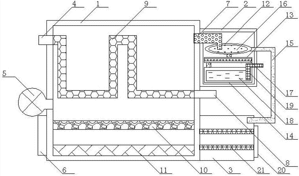
[0013] As shown in the figure, a new type of environmentally friendly boiler includes a furnace body 1, a clean room 2, and a preheating room 3. The left side of the furnace body 1 is sequentially equipped with a water inlet pipe 4, a blast device 5, and a cleaning door 6. The upper end of the right side of the body of furnace 1 is connected to the clean room 2 through the flue gas pipe 7, the middle end of the right side of the body of furnace 1 is equipped with a water outlet pipe 8, and the lower end of the right side of the body of furnace 1 is equipped with a preheating chamber 3; Inside the body 1, a heating elbow 9, a fire grate 10 and an ash cleaning box 11 are sequentially installed from top to bottom; the right end of the water inlet pipe 4 is connected to the left end of the heating elbow 9, and the right end of the heating elbow 9 is connected to the Outlet pipe 8 left end nozzles.

Embodiment 2

[0015] As shown in the figure, a heat exchange area 12, a filter area 13, and a water bath area 14 are sequentially arranged inside the clean room 2 from top to bottom, and the bottom end of the heat exchange area 12 is connected to the filter area 13 through a flue gas pipe 7. The bottom end of the filter area 13 is connected to the water bath area 14 through the flue gas pipe 7; the right end of the heat exchange area 12 is connected to the preheating chamber 3 through the heat transfer pipe 15; the heat exchanger 16 is installed inside the heat exchange area 12, and the filter area 13 An activated carbon filter stick 17 is installed inside, and a miniature water tank 18 is installed inside the water bath area 14; a smoke exhaust pipe 19 is installed on the right side of the miniature water tank 18.

Embodiment 3

[0017] As shown in the figure, a feed door 20 is installed on the right side of the preheating chamber 3 , and a stainless steel filter screen 21 is installed inside the preheating chamber 3 .


PUM


Abstract

A new type of environmentally friendly boiler, including a furnace body, a purification chamber, and a preheating chamber. The left side of the furnace body is sequentially equipped with a water inlet pipe, a blower device, and a cleaning door. The upper end of the furnace body is passed through a flue gas pipe. Connected to the clean room, the middle end of the right side of the furnace body is equipped with a water outlet pipe, and the lower end of the right side of the furnace body is equipped with a preheating chamber; the inside of the furnace body is sequentially equipped with a heating elbow, a fire grate and an ash cleaning box from top to bottom; The nozzle at the right end of the water inlet pipe is connected to the nozzle at the left end of the heating elbow, and the nozzle at the right end of the heating elbow is connected to the nozzle at the left end of the water outlet pipe. The invention has simple structure and high thermal efficiency, uses waste heat of flue gas as fuel for waste heat, fully burns the fuel, and reduces use cost; filters and purifies the flue gas, reduces the content of dust and harmful gases in the flue gas, and has the advantages of energy saving The advantages of environmental protection, safety and sanitation; and can realize rapid heating, and it is more convenient to clean the sanitation inside the furnace body.

Description

technical field [0001] The invention relates to a civil boiler, in particular to a novel environment-friendly boiler. Background technique [0002] In most rural areas in northern my country, collective heating has not yet been realized. People use coal, straw, and boilers for heating at home. Therefore, heating in winter in northern rural areas is an urgent problem to be solved. While heating is achieved by burning coal and boilers, the harmful gases produced by fuel combustion have caused certain pollution to the environment, and most of the boilers used by people are coal-burning or straw-burning boilers, which have low combustion efficiency and are wasteful. Insufficient combustion, the exhausted flue gas also contains many harmful gases or dust that are not conducive to the human body, threatening people's health; the direct emission of flue gas will also Causes the loss of a large amount of heat in the flue gas, resulting in waste of resources. If the air quality ...

Claims


Application Information

Patent Timeline
IPC IPC(8): F24H1/44B01D50/00B01D53/18
Inventor 谷哲学
Owner HARBIN JINJING BOILER
Why Eureka
Try Eureka