Magnetic resonance imaging (MRI) testing die body assembly

A magnetic resonance imaging and phantom technology, applied in the direction of measuring devices, measuring electrical variables, instruments, etc., can solve the problem of lack of test phantoms, and achieve the effect of convenient testing and comparability

Active Publication Date: 2018-01-05
SHANGHAI UNITED IMAGING HEALTHCARE
View PDF8 Cites 20 Cited by
  • Summary
  • Abstract
  • Description
  • Claims
  • Application Information

AI Technical Summary

Problems solved by technology

[0004] At present, there are Magphan SMR series phantoms of the American Association of Physicists in Medicine (AAPM) and the ACR MRI phantom phantoms of the American College of Radiology (ACR). These two phantoms are compatible with Their respective MRI test standards correspond, but the standards of these two institutions have not yet been fully introduced into the country
[0005] At present, the current domestic standard for the determination of image quality parameters of magnetic resonance equipment - YY / T0482-2010 "Determination of main image quality parameters of medical imaging magnetic resonance equipment" is transformed from the International Electrotechnical Commission (International Electrotechnical Commission, IEC) IEC62464-1 : 2007, mainly measuring the six parameters of signal-to-noise ratio, uniformity, layer thickness of two-dimensional scanning, spatial resolution, two-dimensional geometric distortion, and ghosting, but currently lacks one or more comprehensive standards for this standard test phantom

Method used


Image

  • Magnetic resonance imaging (MRI) testing die body assembly
  • Magnetic resonance imaging (MRI) testing die body assembly
  • Magnetic resonance imaging (MRI) testing die body assembly

Examples


Embodiment Construction

[0033] The following will clearly and completely describe the technical solutions in the embodiments of the present invention with reference to the accompanying drawings in the embodiments of the present invention. Obviously, the described embodiments are only some, not all, embodiments of the present invention. Based on the embodiments of the present invention, all other embodiments obtained by persons of ordinary skill in the art without making creative efforts belong to the protection scope of the present invention.

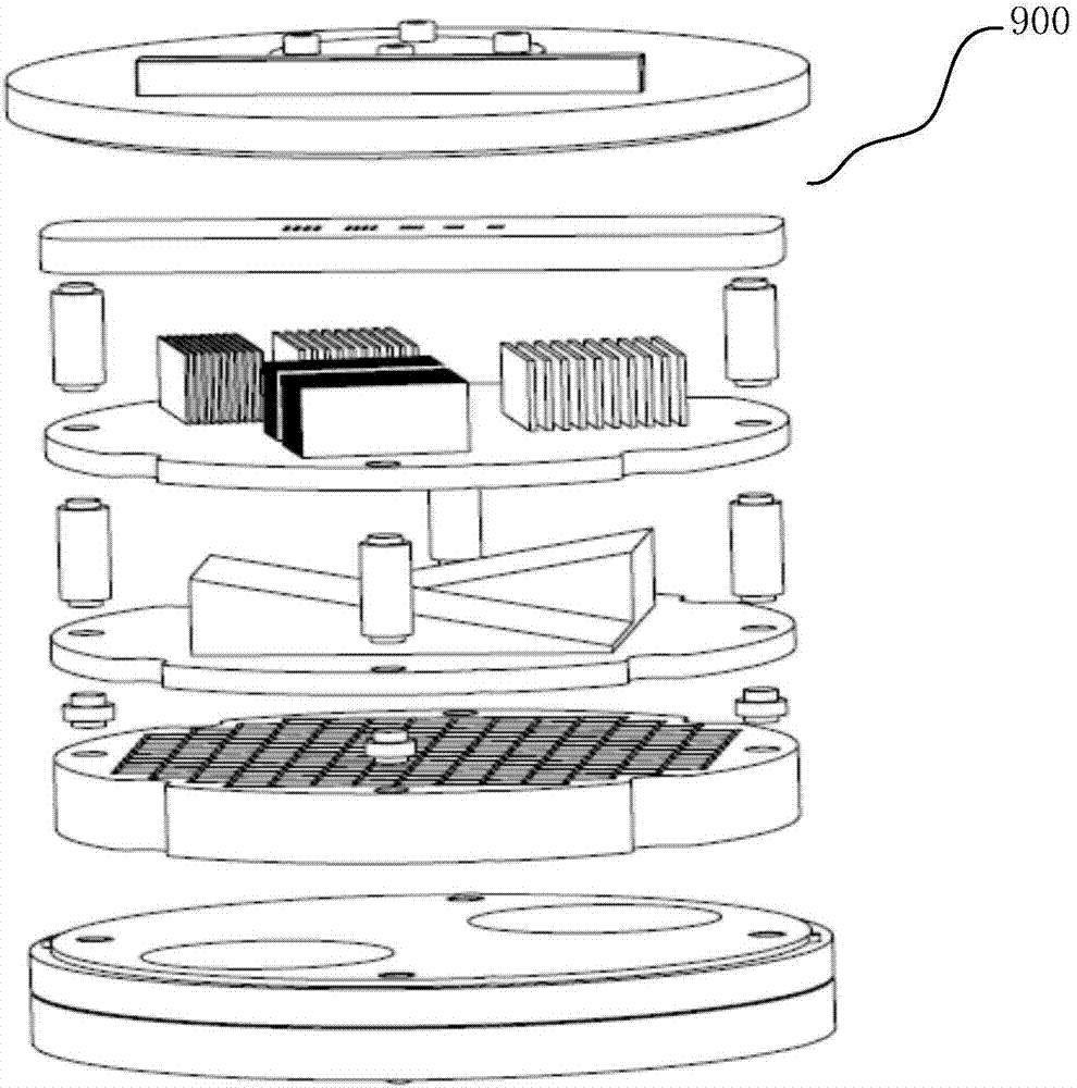
[0034] like figure 1 As shown, a magnetic resonance imaging test phantom assembly 900 includes several modules arranged at intervals in the axial direction (up and down), and each module is used to complete one or more image quality measures of the magnetic resonance imaging system. test.

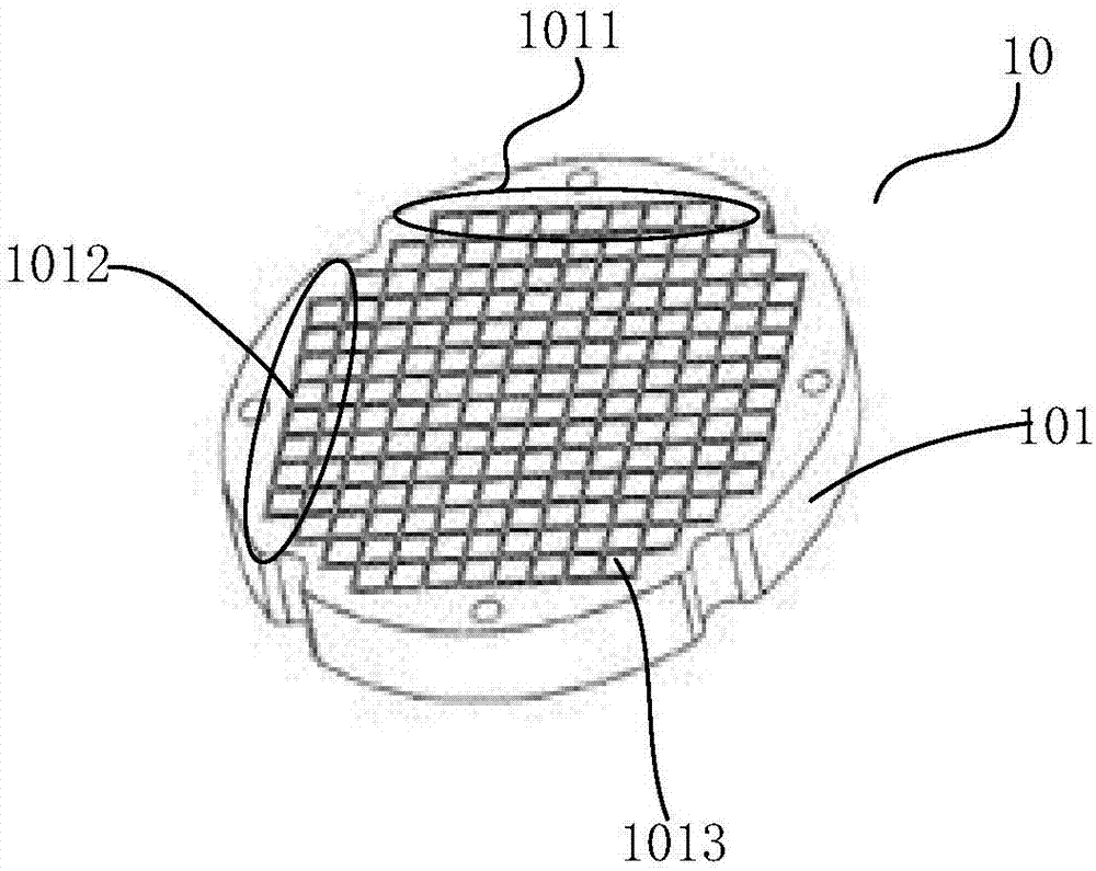
[0035] like figure 2 As shown, the magnetic resonance imaging test phantom assembly 900 includes a first module 10 for testing geometric distortion, and the first phanto...


PUM


Abstract

The invention provides a magnetic resonance imaging (MRI) testing die body assembly. The magnetic resonance imaging testing die body assembly comprises a plurality of modules which are vertically arranged at intervals, wherein each module is used for finishing one or more image quality tests of an MRI system, and also comprises a first module used for testing geometric distortion and a first bearing body which is of a plate structure; first groove channels and second groove channels are arranged in the first bearing body and are respectively extended along a first direction and a second direction. The first groove channels are intersected with the second groove channels to form a grid structure. Hole-shaped structures which are extended along a third direction are formed in cross points ofthe first groove channels and the second groove channels. Compared with the prior art, the magnetic resonance imaging (MRI) test die body assembly can be used by one or in random combinations by multiple die body assemblies. The multiple MRI test die body assemblies form a so-called general test die body. The general testing die body organically integrates various testing modules into one die body, which is easy to test and carry and provides convenience to hospitals performing MRI device quality control and quality guarantee. The general testing die body makes the environment where multipletesting modules are positioned is unified, unifies testing conditions and makes testing data more comparable.

Description

technical field [0001] The invention relates to the field of magnetic resonance imaging, in particular to a magnetic resonance imaging test phantom assembly. Background technique [0002] Magnetic resonance imaging test phantoms play a very important role in the performance testing, quality control (QC) and quality assurance (QA) of magnetic resonance systems. Currently, there are various magnetic resonance test phantoms for different tests items and test methods. [0003] General test phantoms are often only aimed at a specific test item or test method, so to complete a comprehensive evaluation of a certain magnetic resonance equipment, it is often necessary to use multiple phantoms, which is inconvenient for testing and carrying, and because the phantoms The size of the body is different, the formula is different, and the change of the load size will also introduce errors or even errors in the test results. Synthetic test phantoms that combine various test modules can ad...

Claims


Application Information

Patent Timeline
Patent Type & Authority Applications(China)
IPC IPC(8): G01R35/00
Inventor 陈劲松李伟才彭钊
Owner SHANGHAI UNITED IMAGING HEALTHCARE
Why Eureka
Try Eureka