
Annular coil winding machine

A technology of toroidal coils and winding machines, which is applied in the manufacture of coils, electrical components, inductors/transformers/magnets, etc. It can solve problems such as slow winding speed, low production efficiency, and unguaranteed product quality, and achieve precise The effect of controlling the number of winding turns, high production efficiency and scientific design

Pending Publication Date: 2018-01-05
佛山市南海区平洲广日电子机械有限公司
View PDF1 Cites 11 Cited by
  • Summary
  • Abstract
  • Description
  • Claims
  • Application Information

AI Technical Summary

Problems solved by technology

Most of the winding machines currently on the market are the same as the technical scheme described in Chinese patent application No. 201110270114.4, named "Toroidal Coil Winding Machine". The coil clamping mechanism of this type of toroidal coil winding machine consists of It consists of three clamping shafts, a clamping shaft opening and closing mechanism, and a clamping sleeve arranged at the upper end of the clamping shaft in contact with the coil. The clamping shaft opening and closing mechanism is set on a base, so that this type of winding The position of the center of the coil of the wire machine is fixed, and the position of the center of the coil cannot be adjusted, so the storage ring always passes through the center of the coil for winding, so that when winding some coils with larger diameters , it will cause the problem of slow winding speed and low production efficiency, which is not conducive to the long-term development of the enterprise; in addition, there is no counter set on the winding machine of this structure, and such a structure cannot accurately control the turns of the coil winding number, so that the quality of the product cannot be guaranteed

Method used

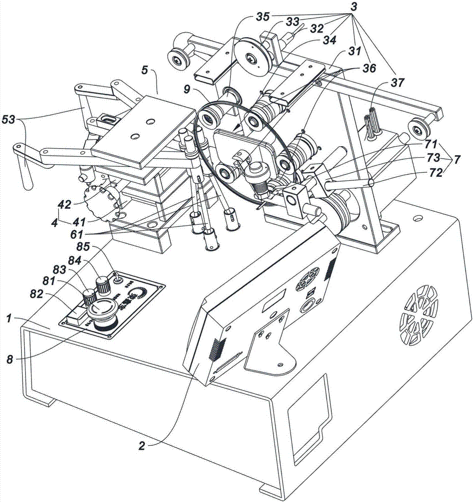
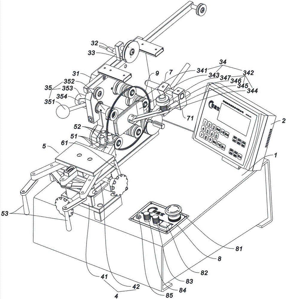
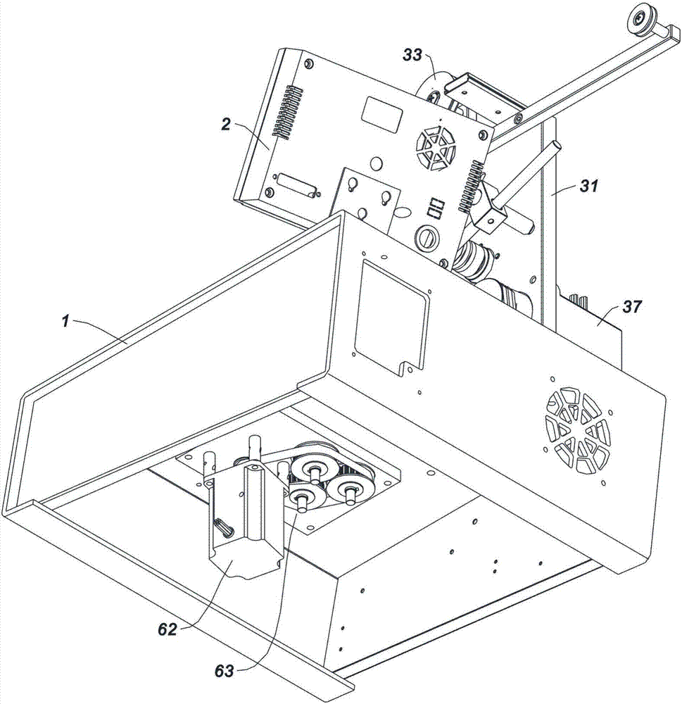

Image

  • Annular coil winding machine
  • Annular coil winding machine
  • Annular coil winding machine

Examples


Embodiment Construction

[0025] Such as figure 1 , figure 2 , image 3 As shown, a ring coil winding machine according to the present invention includes a workbench 1, a controller 2, a winding actuator 3, a coil adjustment mechanism 4, a coil clamping mechanism 5, and a coil rotation mechanism, wherein: the coil The adjustment mechanism 4 includes a front and rear adjustment assembly 41 and a left and right adjustment assembly 42. The front and rear adjustment assembly 41 is installed on the workbench 1. The left and right adjustment assembly 42 is installed on the front and rear adjustment assembly 41 and moves forward and backward through the front and rear adjustment assembly 41. The coil clamping mechanism 5 is installed on the left and right adjustment components 42 and moves left and right through the left and right adjustment components 42. The coil clamping mechanism 5 is provided with three elastic jaws 51, and the front ends of each elastic jaws 51 are respectively set There are rubber w...


PUM


Abstract

The invention relates to an annular coil winding machine. The annular coil winding machine comprises a workbench, a controller, a winding execution mechanism, a coil adjustment mechanism, a coil clamping and supporting mechanism and a coil rotation mechanism, a front and back adjustment component which is arranged on the coil adjustment mechanism is installed on the workbench, and a transverse adjustment component which is arranged on the coil adjustment mechanism is installed on the front and back adjustment component; the coil clamping and supporting mechanism is installed on the transverseadjustment component, and three rubber wheels are arranged on the coil clamping and supporting mechanism; the coil rotation mechanism is used for driving the three rubber wheels to rotate; the windingexecution mechanism comprises a supporting plate, a counter, a reel, a wire clamping component and a wire storage ring opening-closing component, and the supporting plate is installed on the workbench; the wire storage ring opening-closing component, the wire clamping component, the reel and the counter are installed on the supporting plate separately; the controller is installed on the workbenchand is connected with a winding motor, the counter and the coil rotation mechanism. The annular coil winding machine has the advantages of being high in production efficiency, is beneficial to development of enterprises and can precisely control the number of winding turns, so that the quality of the product is guaranteed.

Description

technical field [0001] The invention relates to the technical field of winding machines, in particular to a ring coil winding machine. Background technique [0002] A winding machine is a device that winds a wire-like object onto a specific workpiece, usually used for copper wire winding. Most of the winding machines currently on the market are the same as the technical scheme described in Chinese patent application No. 201110270114.4, named "Toroidal Coil Winding Machine". The coil clamping mechanism of this type of toroidal coil winding machine consists of It consists of three clamping shafts, a clamping shaft opening and closing mechanism, and a clamping sleeve arranged at the upper end of the clamping shaft in contact with the coil. The clamping shaft opening and closing mechanism is set on a base, so that this type of winding The position of the center of the coil of the wire machine is fixed, and the position of the center of the coil cannot be adjusted, so the storag...

Claims


Application Information

Patent Timeline
IPC IPC(8): H01F41/066H01F41/08H01F41/082H01F41/098
Inventor 袁华枝周浩华段新合谢嘉杰袁国辉严詠瑜
Owner 佛山市南海区平洲广日电子机械有限公司
Learn More