Handheld mulberry field shoot harvester
A cutting machine and hand-held technology, which is applied in the field of hand-held mulberry cutting machines, can solve the problems of heavy scissors, heavy pruners, overturning of support rods, etc., and achieve good adaptability, simple operation, and satisfactory The effect of pruning requirements
- Summary
- Abstract
- Description
- Claims
- Application Information
AI Technical Summary
Problems solved by technology
Method used
Image

Examples
Embodiment 1
[0025] Embodiment 1, combining figure 1 ;
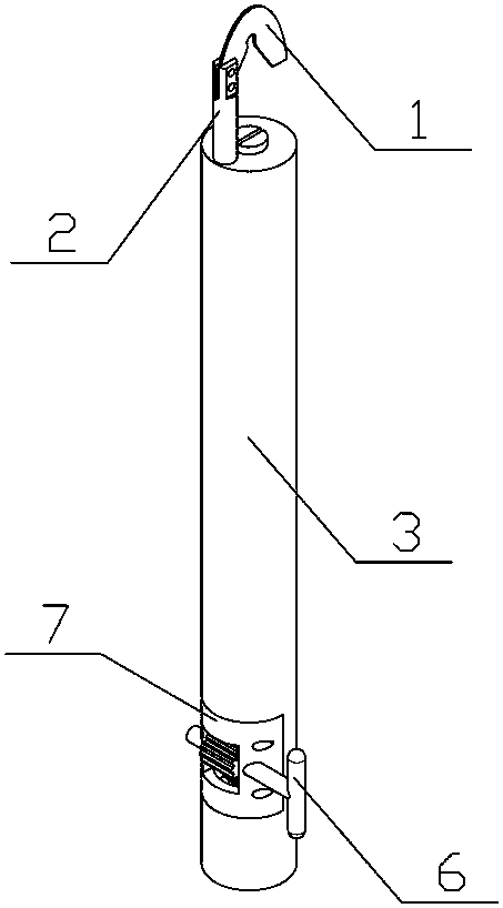
[0026] A hand-held mulberry field cutting machine, including a blade (1), a connecting column (2) and a hand-held rod (3), characterized in that: the shape of the blade (1) is semi-elliptical, and its interior is an inverted V type cutting edge (1.1), one end of the blade (1) is a connecting part, the connecting part of the blade (1) and the upper part of the connecting column (2) are detachably fastened together, the blade The other end is a free end, which is open, and the lower part of the connecting column (2) is welded together with the top of the handle bar (3).
[0027] Hold the handle bar (3) with your hand, extend the inverted V-shaped cutting edge (1.1) of the blade (1) from the opening of the blade to the root of the branch to be trimmed, and pull the hand-held mulberry harvester down to facilitate Remove branches that need pruning.
Embodiment 2
[0028] Example 2, combined with figure 1 and figure 2 ;
[0029] On the basis of Example 1, the connecting part of the blade (1) is provided with two fixing holes (1.2), and the upper part of the connecting column (2) is provided with a relief groove (2.1) along the axial direction, so The connection part of the blade (1) is placed in the relief groove (2.1), and the upper part of the connection column (2) is also provided with two connection holes that match the fixing holes (1.2) of the blade (1) (2.2), the fixing bolt passes through the connecting hole (2.2) and the fixing hole (1.2) to fasten the blade (1) and the connecting column (2) together.
[0030] The blade is fixed on the connecting column by means of bolt clamping, which is convenient for replacement and maintenance.
Embodiment 3
[0031] Example 3, combined with Figure 1-Figure 4 ;
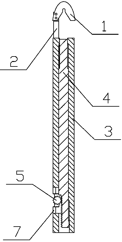
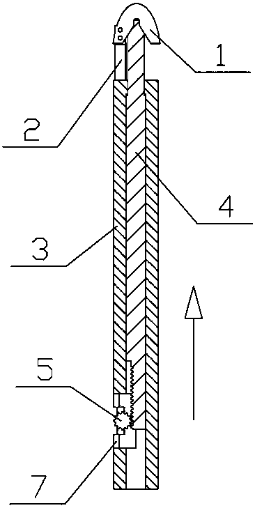
[0032] On the basis of Example 2, it also includes a push rod (4), a gear (5), a handle (6) and a cover plate (7), the handle rod (3) is a hollow structure, and the handle rod (3) ) is provided with a groove (3.1) at the bottom, and a guide groove (3.2) at the bottom, the ejector rod (4) is placed in the handle rod (3), and the ejector rod (4) is a stepped cylindrical shape , the upper part is small and the lower part is large, the lower end of the ejector rod (4) is provided with a transmission rack (4.1) and a guide protrusion (4.2), and the guide protrusion (4.2) is placed in the guide groove (3.1 ) inside, the upper part of the ejector rod (4) is provided with a cutting edge relief groove (4.3), the crank handle (6) is T-shaped, and the gear (5) communicates with the crank handle (6) The cover plate (7) is connected together, the gear (5) is meshed with the transmission rack (4.1), the section of the cover plate (7) ...
PUM
 Abstract
Description
Claims
Application Information
 - R&D
- Intellectual Property
- Life Sciences
- Materials
- Tech Scout
- Unparalleled Data Quality
- Higher Quality Content
- 60% Fewer Hallucinations
Browse by: Latest US Patents, China's latest patents, Technical Efficacy Thesaurus, Application Domain, Technology Topic, Popular Technical Reports.
© 2025 PatSnap. All rights reserved.Legal|Privacy policy|Modern Slavery Act Transparency Statement|Sitemap|About US| Contact US: help@patsnap.com