

Vacuum defoaming device and foam removal method adopting device
A vacuum defoaming and control device technology, applied in the direction of foam dispersion/prevention, can solve problems such as difficult continuous defoaming, matching problems, adverse reactions of raw materials, etc., to solve adverse effects, reduce the number of bubbles, and improve defoaming effect of ability
- Summary
- Abstract
- Description
- Claims
- Application Information
AI Technical Summary
Problems solved by technology
Method used
Image


Examples
Embodiment Construction
[0019] The specific implementation of the vacuum degassing device provided by the present invention and the bubble removal method using the vacuum degassing device will be described in detail below in conjunction with the accompanying drawings.
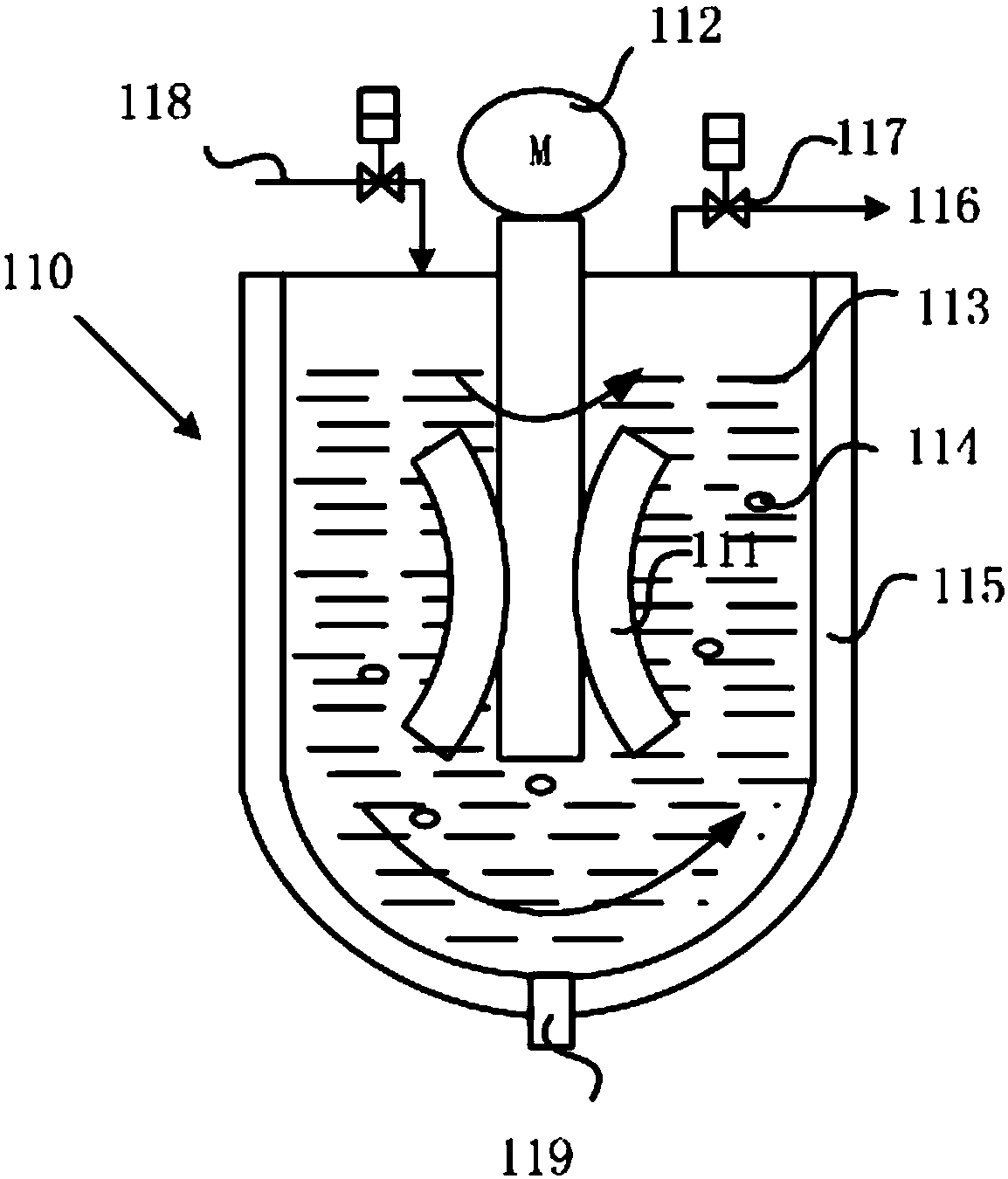
[0020] see figure 1 As shown, an embodiment of the present invention provides a vacuum defoaming device, which includes: a tank body 110, a stirring shaft 111 and a control device (not marked in the figure).
[0021] Wherein, the tank body 110 is used to contain the liquid material 113 , and when the tank body 110 rotates (clockwise or counterclockwise), the liquid material 113 is centrifugally moved along with the tank body 110 .
[0022] The stirring shaft 111 is disposed in the tank body 110 . When the stirring shaft 111 rotates, the liquid material 113 is stirred, so that the liquid material 113 performs centrifugal motion.
[0023] The control device is respectively connected with the tank body 110 and the stirring shaft 111 fo...
PUM
 Abstract
Description
Claims
Application Information