Punch feeding and discharging auxiliary device

An auxiliary device, punching technology, applied in the direction of feeding device, positioning device, storage device, etc., can solve the problems of boring working process, increasing motor power and moment of inertia, occupying large volume, etc., to reduce the frequency, shorten the movement distance, The effect of increasing the number of sheets

Pending Publication Date: 2018-01-09
ANHUI HISEED ROBOT CO LTD
View PDF1 Cites 2 Cited by
  • Summary
  • Abstract
  • Description
  • Claims
  • Application Information

AI Technical Summary

Problems solved by technology

The disadvantages of this method of operation: the working process is boring, the labor intensity of the workers is high, fatigue is easy to occur, the work rhythm is fast, and the labor cost is high.
Since each punching machine can only complete one process, but a sheet needs to complete multiple processes, so a large number of workers are required to operate the punching machine, which greatly increases the labor cost of the enterprise
Moreover, due to the mechanical and repetitive nature of the work, it is easy to cause various safety accidents.
Chinese patent CN 104607566 B introduces a punching machine loading and unloading auxiliary equipment device, which uses a PLC control module to control all actions of the punching machine loading and unloading auxiliary equipment device. The device is essentially a three-degree-of-freedom stamping robot, occupying a Larger, the power line and the control line are placed in the first synchronous belt and the second synchronous belt. When the end effector is in motion, it needs to drag the second tank chain and the second tank chain to move, the second tank chain and the second tank chain. The mass of the tank chain itself is relatively large. In the case of the same load, the power and moment of inertia of the motor need to be increased. When the weight and volume of the plate itself are small, the use of stamping robots will cause a certain waste of resources.

Method used


Image

  • Punch feeding and discharging auxiliary device
  • Punch feeding and discharging auxiliary device

Examples


Embodiment Construction

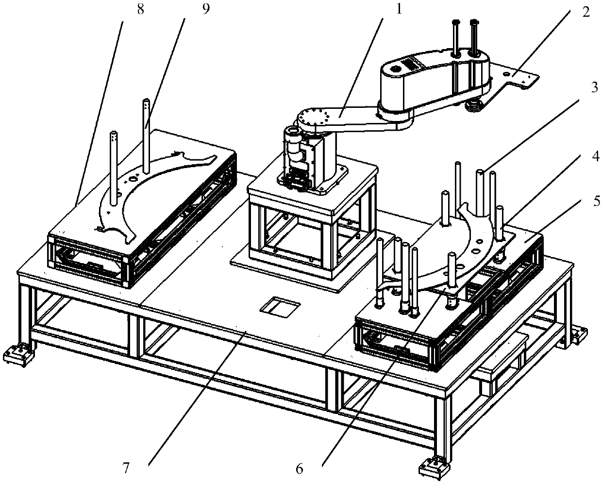
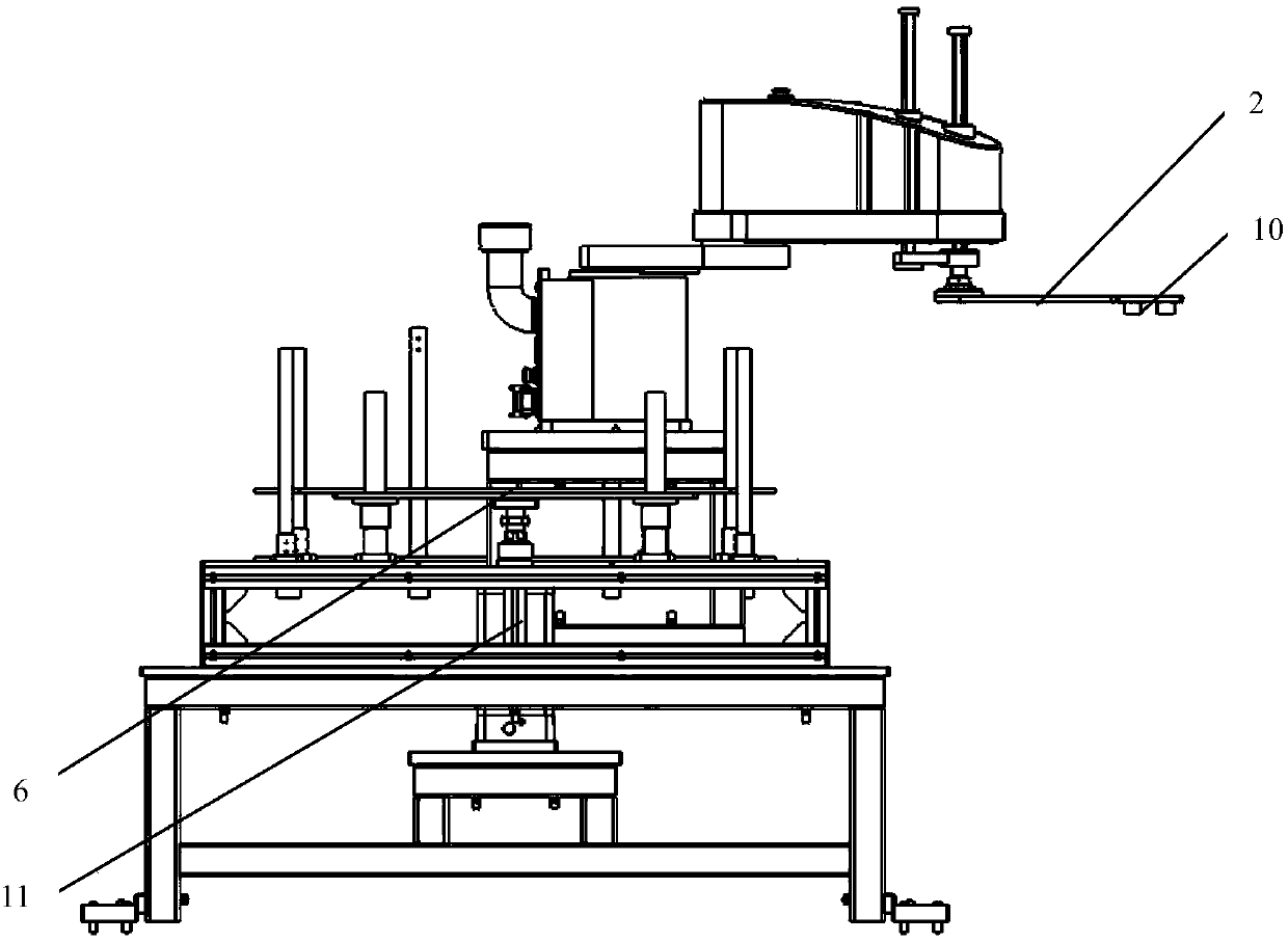
[0012] like Figure 1-Figure 2 As shown, an auxiliary device for loading and unloading on a punching machine includes an installation stand 7, a control cabinet, a four-axis industrial robot 1, a feeding tray and an unloading tray, and the control cabinet is fixed on the bottom of the installation stand 7. In this embodiment, the four The four-axis industrial robot 1 is a SCARA robot, the four-axis industrial robot 1 is installed on the installation stand 7, the end mounting plate 2 is fixed on the end effector of the four-axis industrial robot 1, and the electromagnetic chuck 10 is installed on the end mounting plate 2. Axis industrial robot 1 is arranged between the feeding tray and the unloading tray.

[0013] The control cabinet includes electrical control components, and the control cabinet is used to control the action process of the entire device.

[0014] The four-axis industrial robot 1 has a degree of freedom of movement in the XYZ direction and a degree of freedom ...


PUM


Abstract

The invention discloses a punch feeding and discharging auxiliary device, and belongs to the technical field of industrial robot application. The device comprises an installing rack, a feeding disc and a discharging disc. A four-axis industrial robot system is arranged on the installing rack. A tail end installing plate is fixed to an end effector of a plane joint robot, an electromagnetic suctioncup is arranged on the tail end installing plate, and the plane joint robot is arranged between the feeding disc and the discharging disc. The feeding disc comprises a feeding disc installing table fixed to the installing rack, a plurality of positioning guide rods are fixedly connected with the feeding disc installing table. The positioning guide rods are arranged on the periphery of a non-punched panel. The discharging disc comprises a discharging disc installing table fixed to the installing rack, a plurality of polished shafts and the discharging disc installing table are fixedly connected, punched panels are hung on the multiple polished shafts, and an SCARA robot body is small in weight, small in occupied size and simple and reliable in positioning.

Description

technical field [0001] The invention belongs to the technical field of industrial robot application, and in particular relates to an auxiliary device for loading and unloading materials on a punching machine. Background technique [0002] The traditional feeding method of stamping machine tools is to manually grab the plate by hand and send it to the workbench of the stamping machine tool. After the punching machine is stamped and formed, the formed plate is manually taken out. The disadvantages of this mode of operation: the work process is boring, the labor intensity of the workers is high, fatigue is easy to occur, the work rhythm is fast, and the labor cost is high. Since each punching machine can only complete one process, but forming a sheet requires multiple processes, a large number of workers are required to operate the punching machine, which greatly increases the labor cost of the enterprise. Moreover, due to the mechanical and repetitive nature of the work, it i...

Claims


Application Information

Patent Timeline
Patent Type & Authority Applications(China)
IPC IPC(8): B21D43/18B21D43/02B21D43/22
Inventor 张良安赵学峰冯卓童震张文勇孙龙
Owner ANHUI HISEED ROBOT CO LTD
Why Eureka
Try Eureka