Drilling device for water pump impeller machining
A technology for drilling devices and water pump impellers, applied in positioning devices, boring/drilling, metal processing equipment, etc., can solve problems such as low work efficiency and low safety, and achieve the effect of improving efficiency
- Summary
- Abstract
- Description
- Claims
- Application Information
AI Technical Summary
Problems solved by technology
Method used
Image
Examples
Embodiment 1
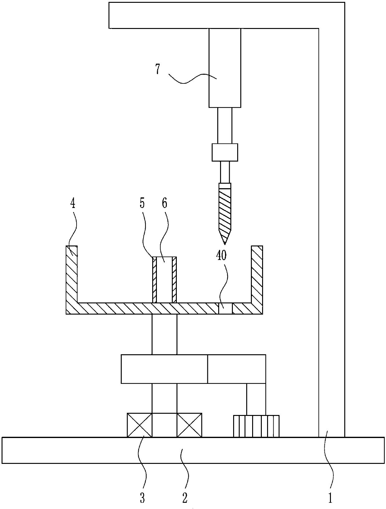
[0029] A drilling device for processing water pump impellers, such as Figure 1-5 As shown, it includes a support 1, a base 2, a rotating mechanism 3, a placement frame 4, a rubber pad 5, a fixed shaft 6 and a drilling mechanism 7, a rotating mechanism 3 is provided in the middle of the top of the base 2, and a rotating mechanism 3 is provided on the top of the rotating mechanism 3. The frame 4 is placed, the middle of the bottom of the frame 4 is provided with a fixed shaft 6, the periphery of the fixed shaft 6 is provided with a rubber pad 5, the right side of the top of the base 2 is connected with a support 1, and the top of the support 1 is provided with a drilling mechanism 7. The hole mechanism 7 is arranged on the upper right side of the placing frame 4 , and a first through hole 40 is opened on the bottom right side of the placing frame 4 .
Embodiment 2
[0031] A drilling device for processing water pump impellers, such as Figure 1-5 As shown, it includes a support 1, a base 2, a rotating mechanism 3, a placement frame 4, a rubber pad 5, a fixed shaft 6 and a drilling mechanism 7, a rotating mechanism 3 is provided in the middle of the top of the base 2, and a rotating mechanism 3 is provided on the top of the rotating mechanism 3. The frame 4 is placed, the middle of the bottom of the frame 4 is provided with a fixed shaft 6, the periphery of the fixed shaft 6 is provided with a rubber pad 5, the right side of the top of the base 2 is connected with a support 1, and the top of the support 1 is provided with a drilling mechanism 7. The hole mechanism 7 is arranged on the upper right side of the placing frame 4 , and a first through hole 40 is opened on the bottom right side of the placing frame 4 .
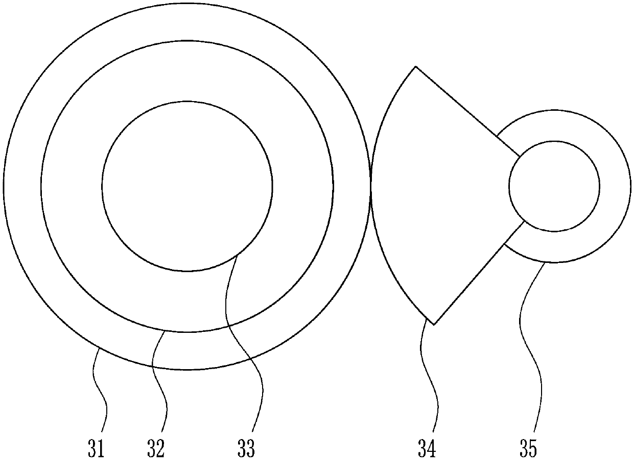
[0032] Turning mechanism 3 comprises bull gear 31, first bearing seat 32, first rotating shaft 33, sector gear 34 and first mot...
Embodiment 3
[0034] A drilling device for processing water pump impellers, such as Figure 1-5 As shown, it includes a support 1, a base 2, a rotating mechanism 3, a placement frame 4, a rubber pad 5, a fixed shaft 6 and a drilling mechanism 7, a rotating mechanism 3 is provided in the middle of the top of the base 2, and a rotating mechanism 3 is provided on the top of the rotating mechanism 3. The frame 4 is placed, the middle of the bottom of the frame 4 is provided with a fixed shaft 6, the periphery of the fixed shaft 6 is provided with a rubber pad 5, the right side of the top of the base 2 is connected with a support 1, and the top of the support 1 is provided with a drilling mechanism 7. The hole mechanism 7 is arranged on the upper right side of the placing frame 4 , and a first through hole 40 is opened on the bottom right side of the placing frame 4 .
[0035]Turning mechanism 3 comprises bull gear 31, first bearing seat 32, first rotating shaft 33, sector gear 34 and first moto...
PUM
 Abstract
Description
Claims
Application Information
 - R&D
- Intellectual Property
- Life Sciences
- Materials
- Tech Scout
- Unparalleled Data Quality
- Higher Quality Content
- 60% Fewer Hallucinations
Browse by: Latest US Patents, China's latest patents, Technical Efficacy Thesaurus, Application Domain, Technology Topic, Popular Technical Reports.
© 2025 PatSnap. All rights reserved.Legal|Privacy policy|Modern Slavery Act Transparency Statement|Sitemap|About US| Contact US: help@patsnap.com


