Flexible clamping device

A flexible clamping and clamping rod technology, applied in the field of manipulators, can solve the problems of complexity, high requirements for workers to operate, and a large fixture positioning mechanism.

Pending Publication Date: 2018-01-09
FOSHAN UNIVERSITY
View PDF0 Cites 17 Cited by
  • Summary
  • Abstract
  • Description
  • Claims
  • Application Information

AI Technical Summary

Problems solved by technology

[0003] Products of various specifications are produced in a production line or workstation, and the subsequent problem is the self-adaptation of the manipulator. The traditional manual method to solve the above problem is: a manipulator plus a fixture to clamp a workpiece product , After the product type and size change, the fixtures are generally replaced, especially in the production of some products that require high positioning accuracy and the size and posture of the workpiece change a lot.

Method used


Image

  • Flexible clamping device
  • Flexible clamping device
  • Flexible clamping device

Examples


Embodiment 1

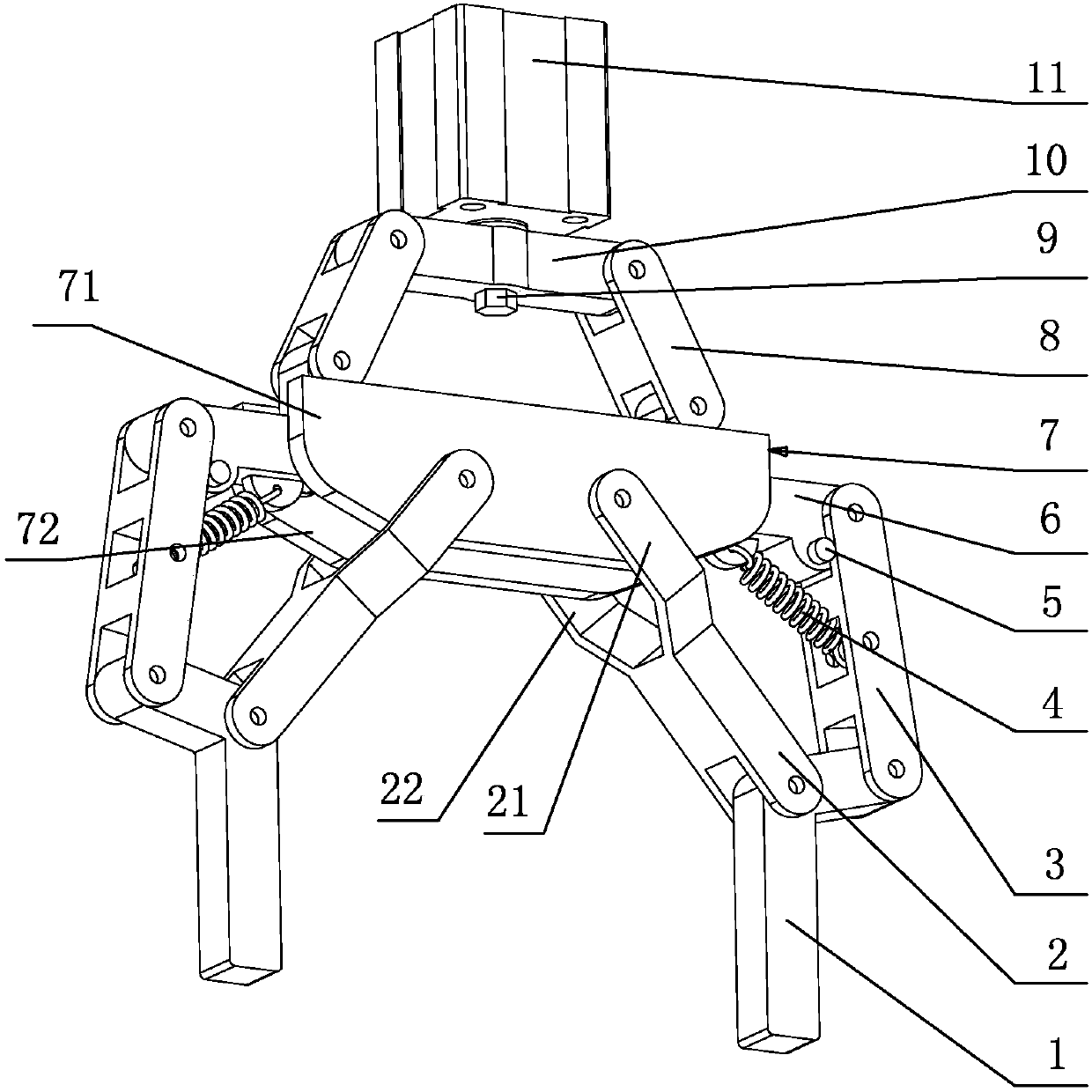
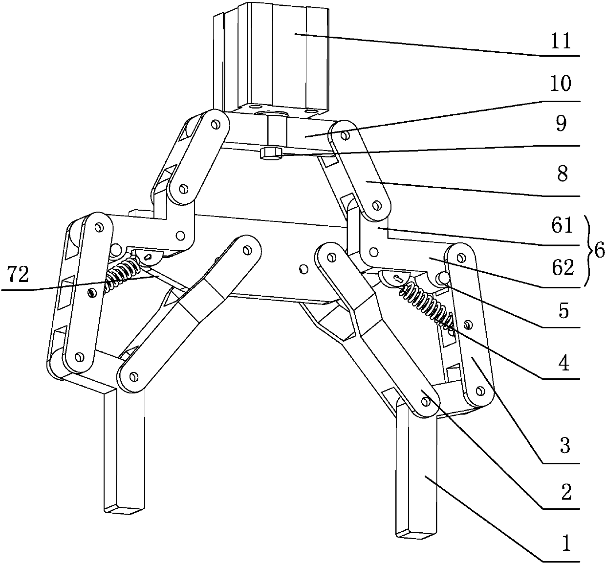
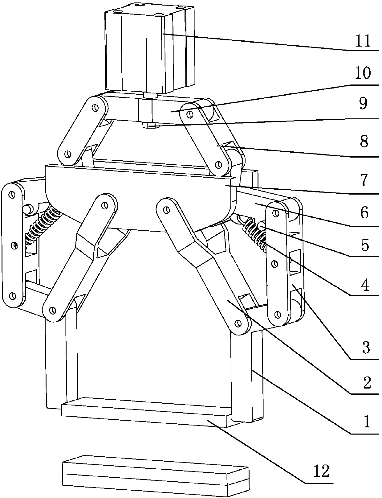
[0048] Such as figure 1 , figure 2 , Figure 9 As shown, a flexible clamping device includes a bracket 7, a driving component and a clamping component, and the driving component drives the clamping component to move;

[0049] The clamping assembly includes two drive links 6 respectively hinged to the bracket 7, two inner links 2 respectively hinged to the bracket 7, and an outer link 3 hinged to the drive link 6, and the outer link 3 is set to two , the two outer connecting rods 3 are respectively hinged to the corresponding drive connecting rod 6, and at the same time are hinged to the clamping rod 1 of the inner connecting rod 2 and the outer connecting rod 3, the clamping rod 1 is set to two, and the two clamping rods 1 are respectively hinged to the corresponding inner connecting rod 2 and outer connecting rod 3;

[0050] Drive assembly comprises cylinder 11, and the cylinder body of cylinder 11 and support 7 positions are relatively fixed, and the cylinder connecting ...

Embodiment 2

[0082] The main structure of this embodiment is the same as that of Embodiment 1, and the similarities will not be repeated here. The difference is that: Image 6 As shown, in order to expand and grab the inner hole object 15, the necessary condition to realize the expansion and grab is: ensure that the clamping rod 1 is vertical in any state. That is, the initial state AECD is a parallelogram. Ensure that DC does not rotate on the plane, that is, the DF rod remains vertical.

[0083] In order to achieve the optimal stable state, the following requirements are put forward for the clamping device:

[0084] Such as Figure 12 As shown, if the model in the state of pinching and grasping at the top is used for expanding grasping, F2c provides a rightward force component to the rod II, and the rod II has a clockwise rotation tendency relative to point B. At this time, the angle θ1 tends to increase, and the limiting element that limits the hinge B is the tension spring 4 .

[0...

Embodiment 3

[0088] The main structure of this embodiment is the same as that of Embodiment 1 or 2, and the similarities will not be repeated here. The difference is that: Figure 7 , Figure 8 As shown, the envelope clamps the large ball 16 and the irregular block 17. To achieve envelope clamping, the movement trend of the clamping rod 1Ⅲ is to move counterclockwise around point D. The movement trend of rod III is shown in Figure 13: when the envelope clamps the object, rod IV is held up by the object, which can be regarded as rod IV has no relative motion to the frame, which can be simplified from Figure 13(a) to Figure 13(b) is a schematic diagram of the mechanism. The mechanism has four components in total, and the corresponding instant center polygon is shown in Figure 13(c).

[0089] It can be known from the instant center polygon that P13 is represented by the common side of △123 and △153, that is, P13 should not only be on the connection line between P12 and P23, but also on the c...


PUM


Abstract

The invention relates to a flexible clamping device, which includes a bracket, a driving component and a clamping component. The driving component drives the clamping component to move; The inner connecting rod is hinged to the outer connecting rod of the driving connecting rod, and the clamping rod is simultaneously hinged to the inner connecting rod and the outer connecting rod. There are two outer connecting rods, and the two outer connecting rods are respectively hinged to the corresponding driving connecting rod. There are two clamping rods, and the two clamping rods are respectively hinged to the corresponding inner and outer connecting rods; a flexible clamping device is composed of underactuated connecting rods, that is, after adding driving elements, any one The unilateral linkage group composed of the driving linkage, outer linkage, inner linkage and clamping lever still has two degrees of freedom, and the underactuated linkage has self-adaptiveness. , it can form the shape of the enveloping object under the action of external force.

Description

technical field [0001] The invention relates to the field of manipulators, in particular to a flexible clamping device. Background technique [0002] In the production process of products, automatic manipulators are widely used in assembly line operations, which can not only improve production efficiency, but also ensure the quality of finished products. [0003] Products of various specifications are produced in a production line or workstation, and the subsequent problem is the self-adaptation of the manipulator. The traditional manual method to solve the above problem is: a manipulator plus a fixture to clamp a workpiece product , After the product type and size change, the fixtures are generally replaced, especially in the production of some products that require high positioning accuracy and the size and posture of the workpiece change a lot. The traditional fixed mechanical fixtures generally need to be adjusted manually. The production mode not only has a complex and...

Claims


Application Information

Patent Timeline
IPC IPC(8): B25J15/08B25J15/00
Inventor 卢清华黄铭贤
Owner FOSHAN UNIVERSITY
Why Eureka
Try Eureka