
Multi-functional stirring machine

A mixer and multi-functional technology, which is applied in cement mixing devices, clay preparation devices, chemical instruments and methods, etc., can solve the problems of limited wear resistance of polyurethane sleeves, affecting the normal operation of equipment, and polyurethane sleeves falling off. Improve the smoothness of discharge and the effect of stable shedding

Inactive Publication Date: 2018-01-09
兰溪市酉泽饲料技术服务有限公司
View PDF8 Cites 2 Cited by
  • Summary
  • Abstract
  • Description
  • Claims
  • Application Information

AI Technical Summary

Problems solved by technology

However, in practical applications, polyurethane sleeves are used on the reverse propeller blades of this device, and the polyurethane sleeves may fall off during work, affecting the normal operation of the equipment. Moreover, the wear resistance of polyurethane sleeves is limited, which may cause wear resistance during long-term work. Reduced abrasiveness

Method used


Image

  • Multi-functional stirring machine
  • Multi-functional stirring machine
  • Multi-functional stirring machine

Examples


Embodiment 1

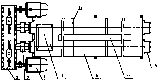
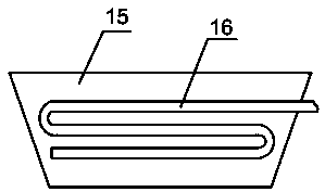
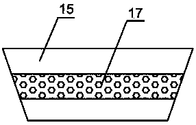
[0021] Such as Figure 1~6 As shown, a multifunctional mixer includes a motor 1 and a mixing box 6, the output shaft of the motor 1 is connected with a reduction box 2, the output shaft of the reduction box 2 is connected with a coupling 3, and the coupling 3 is connected with a stirring shaft 4, and the stirring The shaft 4 is set in the stirring box 6, the motor 1, the reduction box 2, the coupling 3 and the stirring shaft 4 are arranged symmetrically around the center line of the stirring box 6 respectively, the head and tail ends of the stirring shaft 4 are provided with brushes 10, and the stirring shaft 4 There are helical blades 7 on the surface, reverse helical blades 8 are arranged at the intervals of the helical blades 7, and a ribbon blade 9 is arranged on the surface of the stirring shaft 4, and the ribbon blade 9 is formed by buckling two semi-discs with grooves , the outer surface of the mixing box 6 is provided with a sound-absorbing layer 13, the upper surface ...

Embodiment 2

[0026] Such as Figure 1~6 As shown, a multi-functional mixer, in actual work, turn on the motor 1, pour the material into the mixing box 6 continuously through the feed port 5, the motor 1 drives the coupling 3 to rotate through the reduction box 2, and the coupling 3 Drive the stirring shaft 4 to rotate, and the two motors 1 turn in the opposite direction and have the same speed, so that the stirring shaft 4 also rotates in the opposite direction but at the same speed, thereby driving the spiral blade 7, the reverse spiral blade 8 and the ribbon on the stirring shaft 4 The blades 9 roll in opposite directions to stir the materials in opposite directions, and also give the materials a forward force while stirring, so that the materials are pushed to the discharge port 15 while being stirred. During the stirring process, the electric heating belt can be used to 14 Heat the material so that the material can be stirred and dried at the same time, reducing the need for equipment....


PUM


Abstract

The invention provides a multi-functional stirring machine. The multi-functional stirring machine comprises motors and a stirring box; reduction gearboxes are connected with output shafts of the motors; couplers are connected with output shafts of the reduction gearboxes and connected with stirring shafts; the stirring shafts are arranged in the stirring box; the motors, the reduction gearboxes, the couplers and the stirring shafts are symmetrically arranged around the center line of the stirring box correspondingly; electric heating tapes are arranged around the surface of the stirring box; and an air circulation plate is arranged in the center of the upper surface of the stirring box. The multi-functional stirring machine is simple in structure connection, convenient to operate, and capable of stably achieving the continuous stirring function, achieving drying at the same time in the stirring process and performing dewatering and dust removal after stirring is finished, the abrasionresistance of the stirring shafts is good, the stirring and flow guide effects are good, the service life is long, and the multi-functional stirring machine is suitable for being applied and popularized.

Description

technical field [0001] The invention relates to a mixer, in particular to a multifunctional mixer. Background technique [0002] Mixer is a kind of construction machinery, which is mainly used for mixing cement, sand, various dry powder mortar and other building materials. It is a shaft with blades that rotates in a cylinder or a tank to mix various raw materials. , to make a mixture or a machine of suitable consistency. There are many kinds of mixers, such as forced mixers, single-shaft mixers, twin-shaft mixers, etc. [0003] Continuous concrete mixer is also called continuous action mixer. This kind of mixer is carried out continuously and uninterrupted whether it is loading, mixing, or unloading. Concrete is delivered from the other end without stopping halfway. [0004] Prior art such as Chinese Invention Patent Authorization Announcement Document, the authorized announcement number is CN 101342766 B, which discloses a continuous powerful mixer, including symmetrical...

Claims


Application Information

Patent Timeline
Patent Type & Authority Applications(China)
IPC IPC(8): B28C5/14B28C5/46
Inventor 孙琦
Owner 兰溪市酉泽饲料技术服务有限公司
Learn More