A landing gear emergency lowering mechanism

A landing gear and driving mechanism technology, applied in the field of aviation landing gear, can solve the problems of complex force transmission, low carrying capacity, and inapplicability, and achieve the effect of direct force transmission, large carrying capacity, and small occupied space

Active Publication Date: 2019-07-19
LANDING GEAR ADVANCED MFG
View PDF6 Cites 2 Cited by
  • Summary
  • Abstract
  • Description
  • Claims
  • Application Information

AI Technical Summary

Problems solved by technology

[0005] Based on the above factors, the traditional emergency lowering mechanism relying on human-mechanical transmission is not suitable for this type of landing gear due to its complex force transmission and low carrying capacity. Special retractable and retractable landing gear emergency lowering mechanism with good force effect and high reliability

Method used


Image

  • A landing gear emergency lowering mechanism
  • A landing gear emergency lowering mechanism
  • A landing gear emergency lowering mechanism

Examples


Embodiment Construction

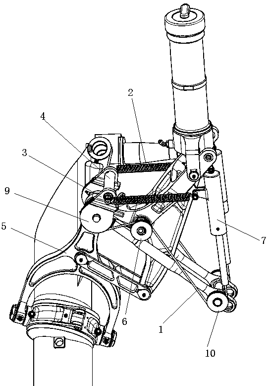
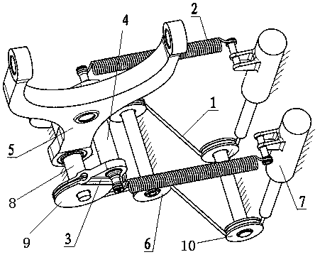
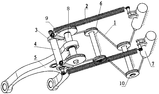
[0031] like Figure 1~3 As shown, a landing gear emergency lowering mechanism includes a rocker arm 5 that can retract and lower the landing gear.

[0032] It also includes a fixed rotating shaft 8, a turntable 9 arranged on the rotating shaft 8 and rotatable around the rotating shaft 8, a support seat 3 arranged on the turntable 9, and a handle 4 fixedly connected to the support seat 3. The turntable 9 is provided with wire slots. The two turntables 9 are arranged symmetrically at both ends of the rotating shaft 8 . The rocker arm 5 is arranged between two turntables 9 . Each turntable 9 is provided with a supporting seat 3, and the two ends of the pull handle 4 are respectively fixed on the supporting seat 3.

[0033] The rocker arm 5 and the rotating shaft 8 are socketed through a bearing. The rotating disk 9 and the rotating shaft 8 are sleeved through bearings.

[0034] It also includes a drive mechanism that drives the turntable 9 to rotate. The driving mechanism i...


PUM


Abstract

The invention discloses an emergent put-down mechanism for an undercarriage. The emergent put-down mechanism comprises a rocker arm capable of retracting and putting down the undercarriage, and further comprises a fixed supported rotating shaft, a rotary plate arranged on the rotating shaft and capable of rotating around the rotating shaft, a supporting base arranged on the rotary plate, and a pulling handle fixedly connected to the supporting base. The rocker arm is connected to the rotating shaft in a sleeving mode and can rotate around the rotating shaft. The emergent put-down mechanism further comprises a driving mechanism for driving the rotary plate to rotate. The emergent put-down mechanism is simple in structural style, high in bearing capacity, direct in force transmission, smallin connecting part quantity, convenient and fast to operate and enough in reliability.

Description

technical field [0001] The invention belongs to the field of aviation landing gear, and in particular relates to an emergency lowering mechanism of the landing gear. Background technique [0002] Chinese patent 201110374199.0 discloses an aircraft main landing gear space retractable mechanism and retractable method, which is independently developed by our company. Due to the small storage space of this type of landing gear, the space retractable form is adopted, and the retractable form is relatively special, and its retractable trajectory is a spatial cone arc. Based on the special retractable form of the landing gear, it brings great difficulty to the design of the emergency lowering mechanism, so that the emergency lowering mechanism was not installed when it was put into production in the early stage, which brought safety hazards to the aircraft. The difficulty in designing the emergency release mechanism is mainly reflected in: [0003] 1. The installation arrangement...

Claims


Application Information

Patent Timeline
Patent Type & Authority Patents(China)
IPC IPC(8): B64C25/30
Inventor 徐达生宁晓东张成亮张航舟金军慕建全钟声李志愿
Owner LANDING GEAR ADVANCED MFG
Why Eureka
Try Eureka